KMC Controls MEP-5073 User Manual
Installation guide, Mounting, Mounting 1
MEP-5061/5063/5065/5071/5073
1
Installation Guide
Mounting
These actuators are designed to mount on a standard
1/2 in. (13 mm) diameter shaft or a 3/8 in. (9.5 mm)
shaft using the optional HFO-0011 adaptor.
Standard Instructions
1. Slide the actuator directly onto the 1/2 in.
diameter damper shaft. The shaft must extend a
minimum of 1-3/4 in. from the mounting surface.
2. Place the non-rotation bracket (supplied) on
the non-rotation tab (see illustration). Leave a
gap of 1/8" between the bottom surface of the
actuator and the bracket to allow for play during
operation.
3. Attach the non-rotation bracket to the mounting
surface using (2) #8 or #10 self-tapping screws
(not included).
4. Depress the gear disengagement button and:
A. Rotate the drive hub until the indicator stops
at the “90” mark if the damper is clockwise
(CW) to close.
B. Rotate the drive hub to the “0” mark if the
damper is counterclockwise (CCW) to close.
5. Position the damper to full open.
6. Torque the two 5/16-18 set screws 75 to 85 in-lb.
7. Depress the gear disengagement button and
rotate the drive hub/damper to the closed
position.
8. Loosen the adjustable end stop, position against
the damper position indicator, and retighten (to 9
in-lb. maximum).
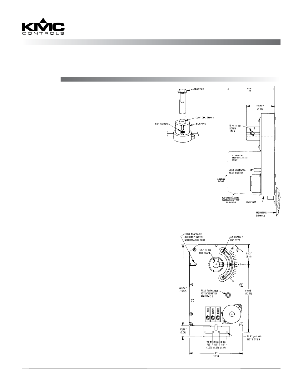
HFO-0011 Adaptor
1. Mount the actuator over the 3/8 in. shaft.
2. Slide the HFO-0011 over the shaft into the drive
hub of the actuator.
3. Align the adaptor slots with the set screws.
4. Partially tighten the set screws.
5. Continue with Step 2 under the Standard
Instructions section above.
Installation Guide
Direct-Coupled, Tri-State, ControlSet Actuators (50 in-lb.)
MEP-5061/5063/5065/5071/5073
HFO-0011 Adaptor
Actuator Side View
Wiring 2
Maintenance 2
Important Notices 2
More Information 2
Actuator Front View
NOTE: On a MEP-
5063/5065/5073,
access to
the gear
disengagement
button is
through the
cover’s access
door.