Linkage to mep–1200 series actuator, Linkage to mep–5000 series actuator, Maintenance – KMC Controls HPO–5213 User Manual
Page 2
HPO–5211/5212/5213
2
Installation Guide
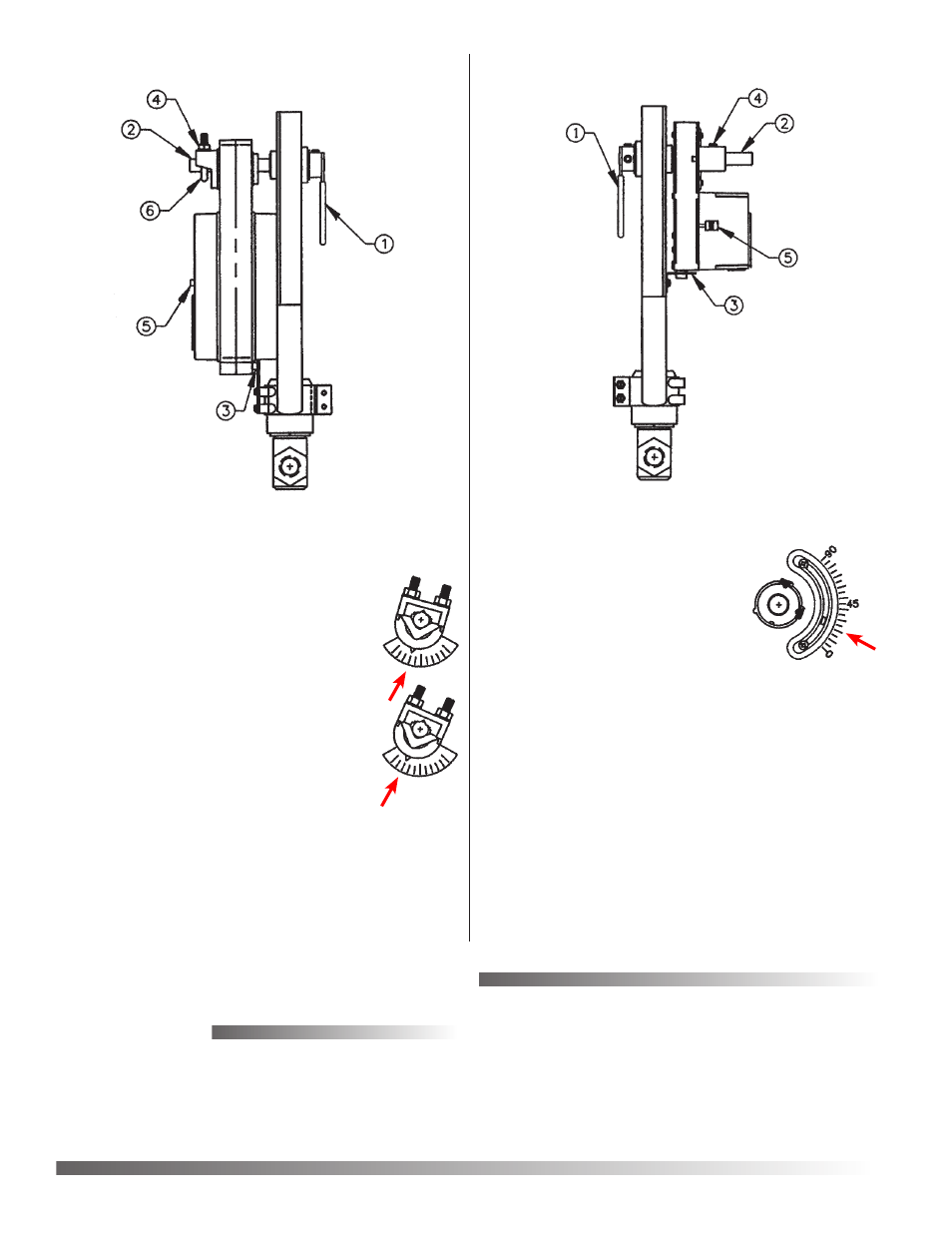
1. Rotate valve linkage lever (1) so that valve stem
(and connecting rod) is in fully
down position.
2. Depress actuators disengagement
button (5) and manually position
actuator pointer between the 20°
and 30° marks.
3. Place actuator over linkage shaft
(2) and non-rotation bracket (3).
4. Tighten 2 setscrews (4) on actuator output hub
while holding linkage lever in position to ensure
valve stem stays fully down.
NOTE: Valve is fully stroked
in each direction with
less than 90° rotation of actuator.
1. Rotate valve linkage lever (1) so that valve stem
(and connecting rod) is in fully down position.
2. Depress disengagement button (5) on actuator and
manually set pointer to the following
position:
For 1/2" through 1-1/4" valves with
HPO–5212 linkage, set pointer at
third mark from full clockwise.
For 1-1/2" through 2" valves with
HPO–5213 linkage, set pointer at
second mark from full clockwise.
3. Place actuator over linkage shaft (2)
and non-rotation pin (3) until cover on
actuator rests against cover on linkage.
4. Finger-tighten 2 coupler nuts (4) until
U-bolt (6) contacts linkage shaft (2).
5. Hold the linkage lever (1) in position to ensure
valve stem stays fully down while evenly torquing
2 coupler nuts (4) to 110–120 in-lbs. Also be sure
actuator cover is held against linkage while
tightening coupler nuts.
NOTE: Valve is fully stroked in each direction with
less than 90° rotation of actuator.
•
•
© 2006 KMC Controls, Inc.
732-019-07B
KMC Controls, Inc.
19476 Industrial Drive
New Paris, IN 46553
574.831.5250
www.kmccontrols.com
Maintenance
No routine maintenance is required. Each compo-
nent is designed for dependable, long-term reliabil-
ity, and performance. Careful installation will also
ensure long-term reliability and performance.
Linkage to MEP–1200 Series Actuator
Linkage to MEP–5000 Series Actuator