Controller connection, Ste-6010/6015, Ste-6011 – KMC Controls STE-6015 User Manual
Page 2: Ste-6013, Maintenance, More information, Controller connection 2, Ste-6010/6015 2, Ste-6011 2, Ste-6013 2
STE-6010/6011/6013/6015 Room Temperature Sensors
2
Installation Guide
STE-6013
STE-6011
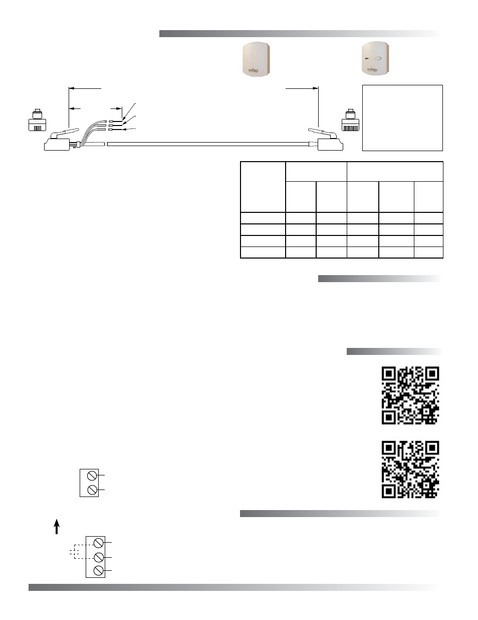
Controller Connection
Connect wires as shown for the relevant model.
Thermistor (10K Ohms)
(Wires are
interchangeable)
Connecting an STE-6010/6015 to a KMC controller
requires a special cable with (on the sensor end) an
RJ-45 modular connector and (on the controller end)
an RJ-11 modular connector with additional wires for
KMC controller inputs. Purchasing pre-assembled
cables from KMC is more cost-effective and reliable
than creating custom cables in the field. Use one of
the following cables:
• KMD-5693 = 25 feet
• KMD-5694 = 50 feet
• KMD-5695 = 75 feet
The additional wire connections to the controller are:
• Orange is the thermistor signal to the controller’s
appropriate input
• Green is the optional 10 VDC supply voltage
from an output of a controller to the STE-6015
LED (for the STE-6010, clip or tape the unused
wire)
• Orange/white should be clipped or taped back
since a setpoint signal is not used with an STE-
6010/6015
NOTE: Pressing the push button (on the STE-
6013/6015) momentarily shunts the
thermistor for a SENSORON signal (via the
C terminal or orange wire).
STE-6010/6015
KMD-5693 = 25 feet; KMD-5694 = 50 feet; KMD-5695 = 75 feet
1
8
Orange Wire = Thermistor Temperature Signal to Controller
Orange/White Wire = Not Used (cut or tape back)
12 inches
5
2
RJ-11 and
Wire Leads
to Controller
RJ-45
to STE
Sensor
Green Wire = 10 VDC Supply Voltage from Controller
(for STE-6015 only; cut or tape back for STE-6010)
RJ-11 RJ-45 Color
(Lead) 8 Orange
7 N.C.
(Lead) 6 Green
3
5
Blue
4
4
Blue/White
5
3
Green/White
2 N.C.
(Lead) 1 Orange/White
(
Cables crossed, 20 AWG
)
Common (“Ground”)
Thermistor (10K Ohms)
D
B
C
10 VDC LED Supply (from Controller)
(Override
Button)
Up (Toward Ceiling at Installation)
Maintenance
Careful installation will also ensure long-term
reliability and performance. Remove dust as neces-
sary from holes in top and bottom. Clean with a soft,
damp cloth and mild soap.
© 2013 KMC Controls, Inc.
866-019-03E
KMC Controls, Inc.
19476 Industrial Drive
New Paris, IN 46553
574.831.5250
www.kmccontrols.com; [email protected]
More Information
Model
Number
Interface
Features
Cable
Connections
Override
Button
LED
Status
Indicator
Screw
Clamp
Terminals
RJ-45
Connector
EIA-485
Data
Port
STE-6010
X
X
STE-6011
X
STE-6013
X
X
X
STE-6015
X
X
X
X
STE-6010/6011
STE-6013/6015
For mounting considerations, net-
work connection, controller con-
figuration, programming, trouble-
shooting, and other information,
.
For general product information,
on the KMC
Controls web site.