Operation, Change setpoint, Change configuration – KMC Controls CTE-5202W User Manual
Page 2
CTE-5202 Electronic Room Thermostat with LCD Display
2
Installation and Operation Guide
Operation
Change Setpoint
To change the setpoint:
1. Push the Setpoint button (or either Up/Down
button) to display the current value.
NOTE: Sequences 2 and 3 have two setpoints
indicated by “snowflake/cool” and “fire/
heat” icons. When the Cooling setpoint is
showing, pushing the Setpoint button will
display the Heating setpoint.
2. Use the Up/Down buttons to change the value.
3. Press the Setpoint button again, and the thermo-
stat will control at the new setpoint. (Alternately,
after about 30 seconds of no activity, the display
reverts back to displaying room temperature.)
Change Configuration
Press and hold both the Up and Down arrows
buttons for about ten seconds until the display starts
flashing “LIMITS.”
NOTE: When a menu is flashing (LIMITS,
ADVANCE
, SYSTEM, or EXIT),
pressing Up or Down displays the next
menu item and pressing Setpoint selects
that menu. When a menu is NOT flashing
(e.g., DEAD BD), pressing Up or Down
changes the value and pressing Setpoint
displays the next menu item.
To change any of the limits (output span) when
“LIMITS” is flashing, press the Setpoint button
until the desired limit (AO1 MIN, AO1 MAX, AO1
AUX
, AO2 MIN, or AO2 MAX) is flashing on the
screen. (Limits are adjustable from 0 to 12 VDC, with
MIN = 0, MAX = 12, and AUX = 0 as defaults.
) Use the
Up and Down buttons to change the desired values.
(If no Auxiliary Flow is desired, set AO1 AUX to 0.)
To change any of the system or advanced features,
press the Up or Down button until the desired (flash-
ing) ADVANCE or SYSTEM menu appears and
then press the Setpoint button.
3. With the hex screws toward the floor, fasten the
backplate to the outlet/handy box with the sup-
plied screws. (The backplate mounts directly on
vertical 2 x 4 inch boxes, but requires an HMO-
1161/HMO-1161W wall plate for horizontal 2 x 4,
4 x 4, or other boxes.)
4. Connect the wires to the terminal block:
• “Heating” output (REE-50xx reheat relay
modules and heating valves) to AO2 and
T
(Common)
• “Cooling” output (VAV dampers and cooling
valves) to AO1 and
T
(Common)*
• Changeover (temperature) sensor (Type III,
10K ohm thermistor) and/or standby/unoccu-
pied setback contact to AI1 and
T
(Common).
(See
External Input (AI1) on page 4
• 24 VAC transformer’s neutral lead to
T
(Com-
mon) and phase lead to
~
. Alternately, 14–35
VDC can be used with + connected to
~
and
– connected to
T
(Common).
*NOTE: For additional wiring details, cross-
references sample applications, and
examples of AO1 being used for heating
instead of or in addition to cooling, see the
5. Place the top of the thermostat over the top of
the mounting base and swing it down over the
hex screw brackets. Be careful not to pinch the
wiring.
6. Back the hex screws out of the backplate brackets
(counterclockwise) until they engage the ther-
mostat and hold it in place.
NOTE: For examples of applications, including
replacing a CTE-510x with the CTE-5202,
see
~
T
T
AO2
“Heating” Output
AO1
“Cooling” Output
Common
Common
Power (AC Phase or DC +)
Input
AI1
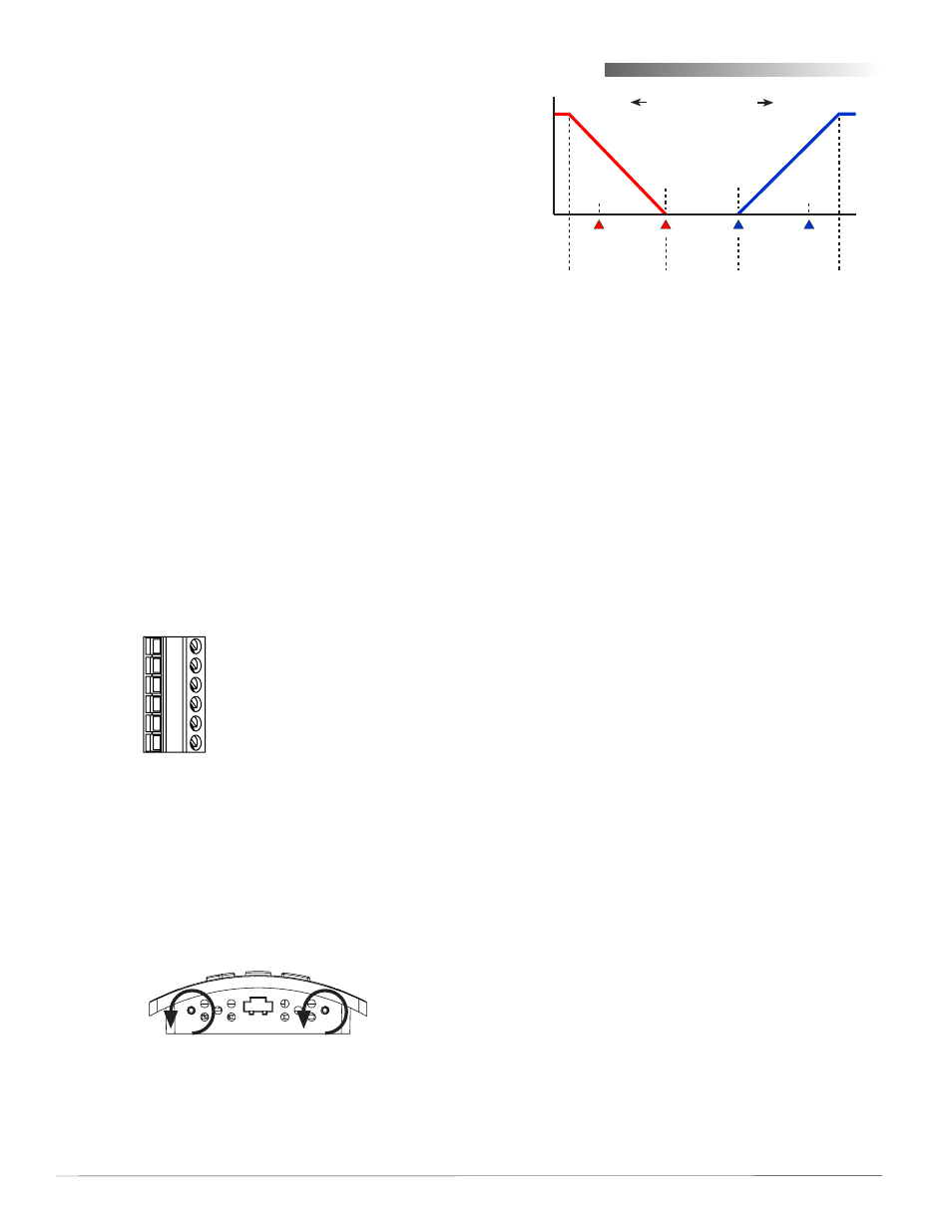
(
Colder
Room Temperature
Warmer
)
Cooling
Setpoint
Heating
Setpoint
Proportional
Band
Proportional
Band
Deadband
(Cooling)
Setback
(Heating)
Setback
Max.
Limit
Min.
Limit
Output
Span