Wiring, Air flow sensor connection, Maintenance – KMC Controls CSP-5002 User Manual
Page 2: Wiring 2, Air flow sensor connection 2, Maintenance 2
CSP-5001/5002
2
Installation Guide
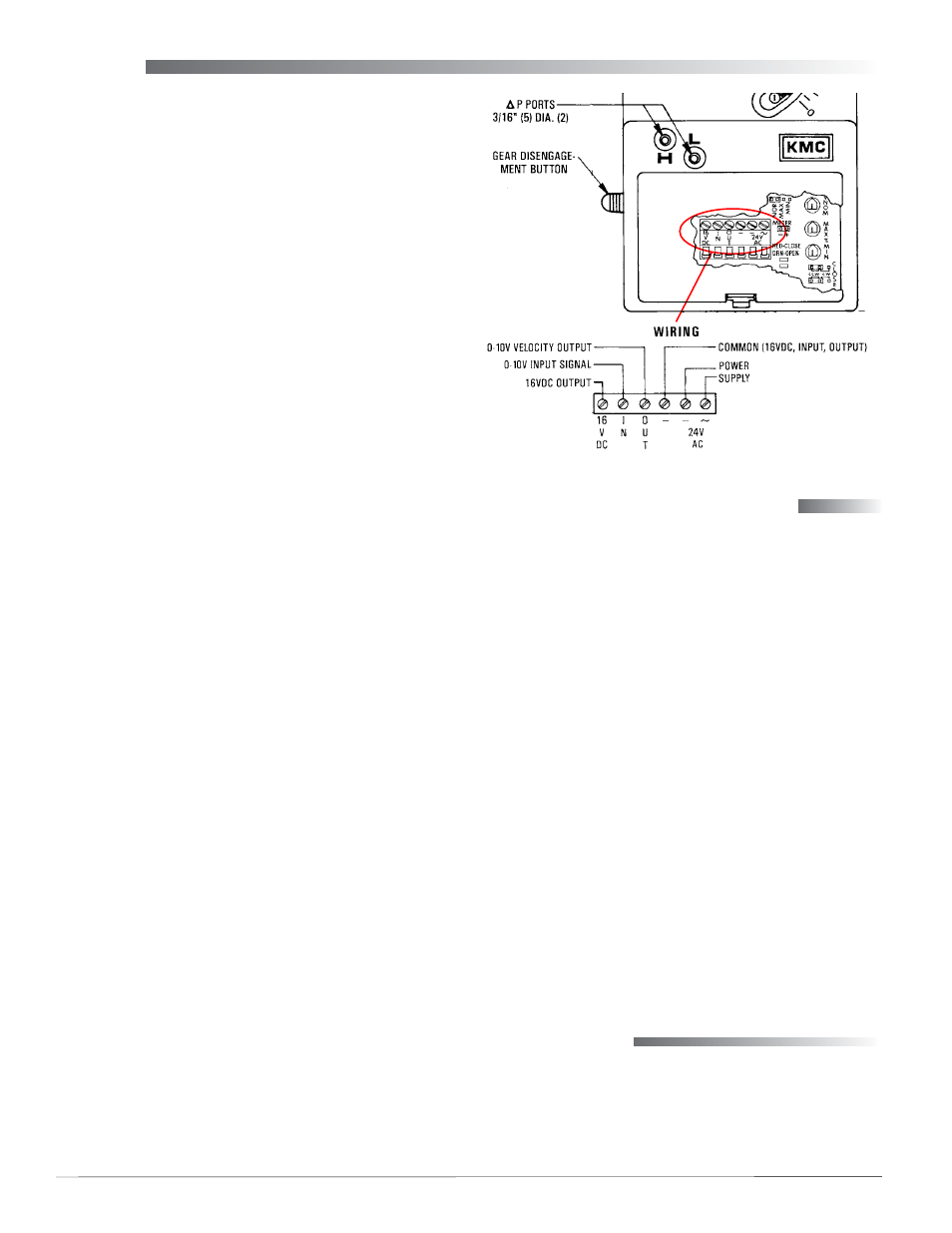
Air Flow Sensor Connection
The CSP-500x is factory calibrated to function with
an SSS-1000 series differential pressure flow sensor.
Using 24" of 1/4" OD x 0.040" wall “FR” instrument
and control tubing, a 3/8" to 1/4" barb union adapter,
and 1" of 3/8" OD x 0.062 “FR” tubing for both con-
nections:
1. Connect the “H” port to the (high side) “H” of the
sensor.
2. Connect the “L” port to the (low side) “L” of the
sensor.
NOTE: To maintain a close correlation with the
factory calibration (for 0 to 3300 fpm), the
3/8" OD tubing between the sensor and the
adapter should be as short as possible, and
the 1/4" OD tubing from the adapter to the
controller should be exactly 24" long (on
both the High and the Low sides) without
other restrictions such as fittings or kinks.
NOTE: The SSS-1000 series differential pressure
flow sensor must be mounted with the
arrow pointing in the direction of the air
flow.
Wiring
1. Remove the CSP-500x's wiring access door by
pulling back on the door’s tab and lifting upward.
2. Access for wire or cable is via two 5/8 in. (16 mm)
diameter snap-in shutter bushings located on the
bottom of the cover.
3. Remove the snap-in shutter bushing and replace
with one the following connectors as needed
(connectors are not supplied—order separately):
A. HMO-4518 for 1/2 in. flexible conduit.
B. HMO-4520 compression connector for plenum
rated cable.
C. HMO-4526 female connector 1/2 in. conduit.
4. Connect the CSP-500x to a CTE-5100 series or a
CTE-5202 thermostat:
A. Terminal “16 VDC” to thermostat terminal “+”
(CTE-5100 series) or “~” (CTE-5202).
B. Terminal “IN” to thermostat terminal “T1/AO1”
for cooling (“T2/AO2” for heating) air flow.
NOTE: If minimum and maximum velocity limits
will be set at the CSP-500x (see
and Maximum Flow Limits on page 4
),
then use “T3” for cooling and “T4” for
heating on a CTE-5100 series thermostat.
C. Terminal “OUT” to thermostat terminal “V1”
for velocity readout at the thermostat.
D. Terminal “–” to thermostat terminal “–/
T
”
(Common).
5. Connect the CSP-500x to a 24 VAC, –15/+20%,
50/60 Hz, 4 VA, Class 2 only power source:
A. Terminal “~” to the phase side of the
transformer.
B. Terminal “–” to the neutral or ground side of
the transformer.
6. Reinsert the wiring access door.
NOTE: For more detailed information about
connections and usage with CTE-5100
.
NOTE: For more detailed information about
connections and usage with newer
CTE-5202 thermostats, see the
Maintenance
No routine maintenance is required. Each compo-
nent is designed for dependable, long-term reliabil-
ity, and performance. Careful installation will also
ensure long-term reliability and performance.