Vfo and premixer (40-59), Receiver (60-79) – Elecraft K1 User Manual
Page 85
3
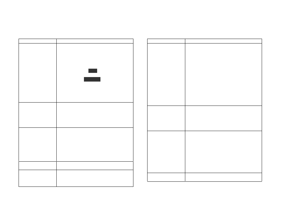
VFO and Premixer (40-59)
Problem
Troubleshooting Steps
40 General VFO
problem; frequency
jumps or drifts
Note: Some VFO drift will always be present
due to aging of components and heating or
cooling of the cabinet
The VFO will drift more if you used the
larger range (C2=120 pF).
Use
C A L
menu entry to check actual VFO
frequency (hold
E D I T
to show the operating
frequency calibration display, then switch to
O S C
using
D I S P L A Y
)
Make sure supply voltage is above 8.5V
If you used solder with water-soluble flux,
clean the board with hot water and a Q-tip
Make sure L1 leads are properly stripped
Check crystals on Filter board
41 Can't tune VFO (or
RIT/XIT offset)
Check actual VFO range (40)
Measure voltage on anode of RF-D3 (VFO
main varactor diode) while tuning VFO pot
Measure voltage on anode of RF-D4 (offset
varactor diode) while tuning the OFFSET pot
Varactors may be installed backwards
42 VFO inductor not
installed or VFO not
oscillating
If you see
E 4 2
, the VFO signal is either
missing or is too low in amplitude to be
counted by the MCU (FP-U1).
Check all VFO components
Check the counter amplifier and related
components (FP-Q1, R11, R12)
Use signal tracing to determine where the
VFO signal is getting lost
45 VFO tunes the
wrong way
VFO pot (FP-R1) CCW and CW leads may
be reversed
46 VFO or RIT/XIT
range is too large, too
small, or shifted
low/high
Check actual VFO range (40)
Varactor diodes may be wrong type
Check all capacitors in VFO, esp. C2 and C7
See Alignment and Test, Part I.
Receiver (60-79)
Problem
Troubleshooting Steps
60 Low (or no) audio
output from receiver,
or general receiver
gain problem
If you hear normal audio output on one band
but not all bands, see 62
Make sure you have headphones or speaker
connected; turn AF GAIN clockwise
Check the key jack for a short to ground
Make sure the attenuator is turned off
Re-peak the band-pass filters
Check for ground shorts in the LPF and BPF
Turn the AF GAIN to maximum. If you don’t
hear any “hiss” at the receiver output,
troubleshoot the AF amplifier (65)
Check the 8V regulated supply voltage and
troubleshoot if necessary (20)
Try using signal tracing (see procedure later
in this section)
62 Signal loss only on
one band
Re-do alignment on affected band
Check the band-pass and low-pass filters and
crystal for this band
Check functioning of the associated relays
(change bands, then measure relay leads that
should be open or shorted for that band)
65 AF amplifier not
working
Use the
S T L
menu entry to set a sidetone
level of 31. If you hear a strong tone, the A.F.
amplifier (RF-U4) is probably working, and
the problem is likely to be with the preamp
(RF-U3) or other RF board circuits.
Signal trace through the receive chain
backwards by touching a tool or wire to
various points along the receive path
Check all DC voltages in the receiver
Inspect the A.F. amp and preamp circuits
70 AGC or S-meter
not working
Make sure the attenuator is off
Check voltages on RF-U1, U2, Q1, Q2, D2