Elecraft K1 User Manual
Page 15
14
E
LECRAFT
i
In the following steps you’ll install toroidal inductors L9-
L12 (type T37-6 cores). They must be wound as indicated in the
instructions, or the transceiver will not operate correctly. Use only
the number of turns specified. It is not necessary to attempt to
precisely match the inductances specified in the parts list.
Find the component outline for L9 on the Filter board.
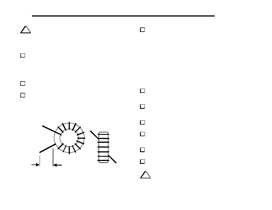
Compare this component outline to Figure 4-3, which shows two
views of a typical toroidal inductor. L9 will be mounted vertically
as shown at the right side of the drawing, with one wire exiting at
the core’s upper left, and the other at the lower right. There are
pads on the PC board in these two locations.
Using the Per-Band Components parts table (Band 1),
determine the number of turns and wire length for L9 and L10.
To wind L9, cut the specified length of #26 red enamel-coated
wire, then "sew" the long end of the wire through the core. Each
pass through the core counts as one turn. The finished winding
should look similar to Figure 4-3, but with the number of turns
indicated in the parts list. Figure 4-3 shows 14 turns.
Remove insulation
Figure 4-3
Verify that the turns of L9 are not bunched together. They
should be evenly spaced, and should occupy about 80-90% of the
core.
Stripping Toroid Leads
The enamel wire supplied with the kit can be heat-stripped. One
way to do this is to place a small amount of solder (a "blob") on the
end of your soldering iron, then insert the wire into the hot solder.
If the iron is hot enough, you should see the insulation vaporize
after 3 to 6 seconds. Another possibility is to burn the insulation
off by heating it with a small butane lighter for a few seconds, then
use fine-grain sandpaper to remove the enamel residue. Avoid
scraping insulation off with a razor blade, as this may nick the wire.
Strip the leads of L9, as explained above. You should remove
the enamel from the leads up to about 1/8" (3 mm) from the core
(Figure 4-3).
Tin L9's leads. The solder should appear clean and shiny. If it
looks dull or is not adhering very well to the bare lead, there is
probably some insulation remaining. Remove it as described above.
Install L9 vertically as shown by its component outline. Pull
the leads taut on the bottom of the board.
Solder the leads of L9. When soldering, make sure that the
solder binds well to the leads. If the lead appears to be an "island" in
a small pool of solder, chances are it is not making good contact.
Wind and install L10 in the same manner as L9, using the
same number of turns. Install L10 vertically, to the right of L9.
Wind and install L11 and L12. Use the Per-Band Components
table (Band 2) to look up the wire length and number of turns.
i
Do not use adhesives or fixatives of any kind to secure L9-
L12 to the PC board. They will be adequately held to the board by
their leads alone.