Elecraft K1 User Manual
Page 24
E
LECRAFT
23
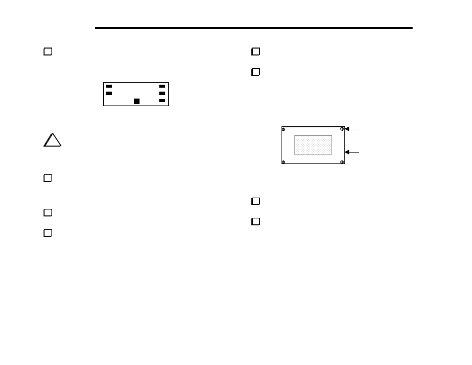
Install caps on switches S1 through S6. S3's cap is square, while
the others are rectangular, as shown in Figure 5-10. The caps are
installed by pressing them onto the switch plungers.
Figure 5-10
i
The LCD's glass surface is protected by a very thin,
nearly invisible piece of protective film. In the following
step, be very careful to remove only the thin film, not the
LCD's glass top. Do not use any type of metallic tool.
Hold the Front Panel PC board assembly under a strong light so
that you can see the surface of the LCD glass clearly. Using a
fingernail, rub one corner of the LCD's glass top to loosen the
protective film, then peel it off.
Locate the front panel chassis piece. Place it on a soft cloth
to protect the finish and labeling.
Some holes in the front panel are masked on the inside surface
during painting. If masking tape (usually green in color) is still
present, you'll need to remove it. To remove masking tape:
Use a blunt instrument such as a ball-point pen to push on the
tape through a hole until the tape begins to lift away.
Peel the tape off, using a sharp tool if necessary. Be careful not
to scratch the outer surface of the panel.
After removing any masking tape, turn the front panel face
up, with the Elecraft logo at the top.
Position the clear plastic LCD bezel over the large LCD
opening, then secure it with four 2-56 screws (stainless steel) as
shown in Figure 5-11. Tighten the 2-56 screws only the amount
needed to hold the bezel to the front panel. Over-tightening may
crack the bezel or strip the threaded holes in the panel.
2-56 Screw (4)
LCD Bezel
Figure 5-11
Remove all hardware from the shaft of the 10-turn
potentiometer (R1). It will be re-attached in a later step.
Locate the 0.75" (19 mm) diameter nylon washer. Place this
washer over R1's threaded bushing.