Elecraft K1 User Manual
Page 39
38
E
LECRAFT
VFO Alignment
Turn the K1 off and disconnect the power supply.
Two different capacitors are supplied for setting the
approximate VFO range: C2 (68 pF disc) and C2A (120 pF
polystyrene). 68 pF provides a range of about 80 kHz; 120-pF
provides a range of about 150 kHz. Other values can also be used
(builder-supplied).
Based on your VFO range selection (page 12), install the
appropriate capacitor at C2. Save the other for possible future use.
If you use the 68-pF disc cap, pre-form the leads to match the pad
spacing for C2.
Wind L1 on a T50-6 toroid core (yellow, 1/2" [12 mm]
diameter). Use 24 inches (61 cm) of red enamel wire. Wind 33
turns on L1, leaving the two leads about 1/2" (12 mm) long.
Adjust the turns of L1 so that they are fairly evenly spaced
and occupy about 90% of the core.
Strip and tin the leads of L1 to within 1/8" (3 mm) of the
core. (Review toroid lead preparation instructions, page 14.)
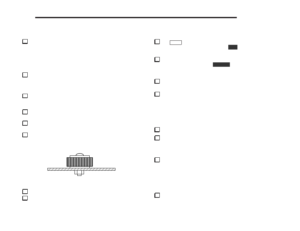
Secure L1 loosely to the PC board as indicated by its
component outline, near J6. As shown in Figure 7-1, use two nylon
washers, a 1/2" (12 mm) nylon screw, and nylon 4-40 nut.
Figure 7-1
Insert L1’s leads into their pads and solder.
Connect the power supply and turn the K1 on.
VFO Range Test
Tap
M E N U
and locate C A L . To enable the operating
frequency calibration display (O P F ), hold
E D I T
. The 100-Hz digit
should be flashing. (If you see E 4 2 , the VFO is not functioning.)
To see the VFO frequency, you’ll use CAL’s other display
mode, O S C . To select this, hold
D I S P L A Y
. You’ll see O S C ,
followed by the VFO frequency in MHz (1 digit), then kHz (3
digits). For example, 3.012 MHz would be shown as 3 , then 0 1 2 .
Make sure that the VFO frequency goes up as the VFO knob is
rotated counter-clockwise. If not, see Troubleshooting.
Rotate the VFO knob fully clockwise until it stops, then note
the frequency: __________ kHz. Rotate it counter-clockwise until
it stops and note the frequency: __________ kHz. Subtract the
low reading from the high reading to obtain the VFO range:
_________ (about 80 or 150 kHz, depending on the value of C2).
VFO Range Adjustment
Make sure the VFO knob is rotated fully counter-clockwise.
If the frequency shown is now higher than 3.100 MHz,
squeeze the turns of L1 (bunch them more closely together) to
lower the frequency. You can squeeze the turns by hand, or use the
tuning tool. Watch the frequency display as you adjust the turns.
If the frequency shown is lower than 3.090 MHz, spread
the turns of L1 out. This raises the VFO frequency. If the frequency
cannot be raised to at least 3.090 by spreading the turns out, you
may need to remove one turn from L1 (the non-grounded end).
Note: The final VFO frequency should be between 3.090 MHz and
3.100 MHz to make sure that the low end of each band is covered.
Once the turns on L1 have been correctly adjusted, tighten the
nylon screw so that the L1’s turns are held firmly in place. (This
may shift the indicated frequency slightly.)