Elecraft K1 User Manual
Page 20
E
LECRAFT
19
i
Before handling ICs and transistors in the following steps,
touch an unpainted, grounded metal surface.
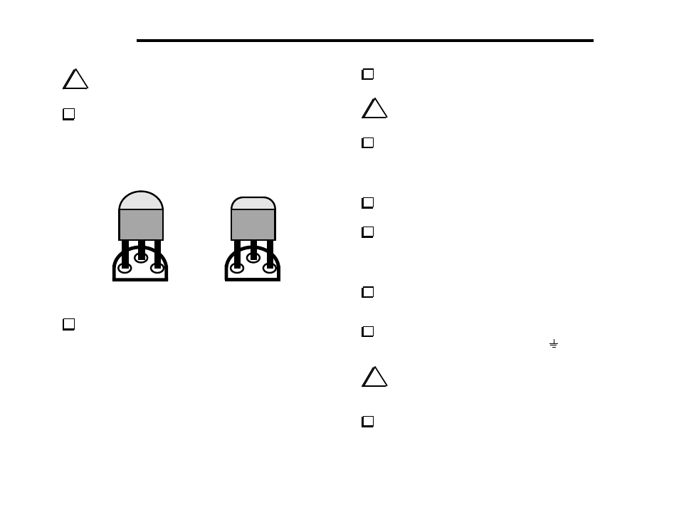
Locate transistor Q1 (type 2N4124), which has a small, 3-lead
TO-92 package. Q1 and other TO-92 devices may have either of
the two shapes shown in Figure 5-4. The right-hand illustration
shows a "modified TO-92" package, which may be labeled on either
the front or back side. The large flat side of each device will be
aligned with the flat side of its component outline.
Figure 5-4
Install Q1 on the bottom side of the board, to the right of the
large hole. Align Q1 as shown above. The transistor should be
mounted about 1/8" (3 mm) above the board; don’t force it down
too far or you may break the leads. Bend the leads outward slightly
to hold Q1 in place, then solder and trim the leads.
Locate U4, a 78L06 voltage regulator, which has a TO-92
package similar to Q1. Install U4 below the large hole.
i
Touch an unpainted, grounded metal surface before
handling the 2N7000 transistor in the next two steps.
Locate the component outline for Q2 (2N7000) on the top
side of the board near the rectangular hole. Q2's outline has the
three pins side-by-side, not in a triangular pattern. Pre-form the
leads of Q2 to match this hole pattern, so that it can be mounted
very close to the PC board with little excess lead length.
Install Q2. Make sure the top of Q2's body is no more
than 0.25" (6 mm) above the board when seated. Solder Q2.
Install the 8-pin ICs, U2 (MAX518), U3 (24LC04), and U5
(LM358) on the bottom side. Orient the notched or dimpled end of
each IC with the notched end of its component outline (see Figure
4-7). Bend two leads outward slightly on the opposite side of the
board to hold the devices in place, but do not solder yet.
Turn to Appendix F (parts placement drawings) to verify that
you have the ICs installed in the proper locations, then solder.
Limit soldering time to 2 to 3 seconds on each lead.
On the top side of the board at the left end you’ll find a short
jumper location, labeled with a ground symbol (
). Install a 3/4"
(19 mm) U-shaped wire here, as you did earlier on the Filter board.
i
The potentiometers to be installed in the next step can be
damaged if you push on their plastic shafts. When seating a
potentiometer, press down only on the metal frame.
Install the two 10-k potentiometers at R2 and R3 (on the top
side of the board). They must be pressed downward until the metal
frame is fully contacting the PC board on both sides. Do not use
excessive heat when soldering.