Rf board, part i – Elecraft K1 User Manual
Page 26
E
LECRAFT
25
6. RF Board, Part I
In Part I, the VFO (variable-frequency oscillator) and receiver
sections will be assembled.
Open the bag labeled RF and sort the components into groups.
Observe anti-static precautions when handling transistors and ICs.
T-R Switch
and Transmitter
VFO
Receiver
J6
J8
J7
AF Amp
Figure 6-1
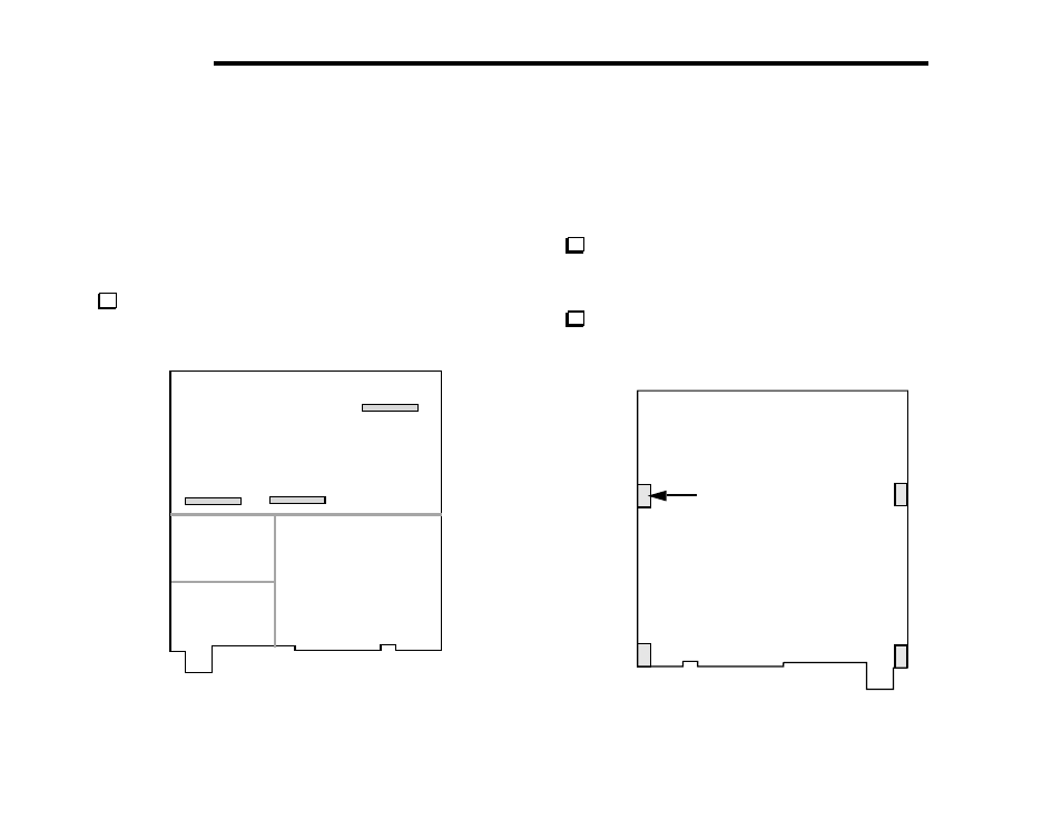
Locate the RF board and orient it as shown in Figure 6-1. This
illustration shows the major areas of the board. Receiver and VFO
circuits occupy the front half; transmitter and T-R switch stages use
the rear half. The Filter board plugs into J6, J7, and J8.
Turn the board over. (Figure 6-2 shows the bottom side.)
Four 2-D fasteners will be attached to the RF board at the indicated
locations to secure it to the chassis panels.
2-D Fastener
Figure 6-2
- KX3 Owner's Manual (58 pages)
- KX3 Assembly Manual (47 pages)
- KX3 Assembly Manual Errata (5 pages)
- KX3-2M (30 pages)
- KX3-PCKT (2 pages)
- KX3 Mobile Installation And Operation Guide (17 pages)
- KX3 Guide for Blind Operators (7 pages)
- KX3 Quick Reference (2 pages)
- K3 Programmers Reference (26 pages)
- KX3 Speaker Grille Instructions (9 pages)
- KXFL3 Filter Option (12 pages)
- KXFL3 Filter Option Errata (2 pages)
- KXAT3 (5 pages)
- KXBC3 (13 pages)
- KXPD3 (4 pages)
- Proset Boom Headset (1 page)
- PX3 Owner's Manual (53 pages)
- PX3 Owners Manual Errata (2 pages)
- KXPA100 Manual (55 pages)
- KXPA100 Assembly Manual (27 pages)
- KXPA100 Assembly Errata (1 page)
- KXPA100 Programmers Reference (24 pages)
- KXAT100 Installation Manual (17 pages)
- KX1 Manual (96 pages)
- KXAT1 (12 pages)
- KXPD1 (7 pages)
- KXB30 (8 pages)
- KXB3080 (20 pages)
- K1 1.09 F/W (1 page)
- KNB1 Manual (8 pages)
- KAT1 Manual (15 pages)
- KFL1-2 (2 pages)
- KTS1 (1 page)
- KBT1 Manual (8 pages)
- KBT1 Manual Errata (2 pages)
- K1BKLTKT LCD Mod Kit (6 pages)
- K2 Owner's Manual (171 pages)
- K2 Owner's Manual Errata (1 page)
- K2 PLL (4 pages)
- K2ATOBKIT (15 pages)
- K2ATOBKT (2 pages)
- K2 Keying Modification Instructions (4 pages)
- KPA100 Manual (74 pages)
- KPA100 Shield Upgrade (3 pages)