Elecraft K1 User Manual
Page 41
40
E
LECRAFT
Band-Pass Filter Alignment
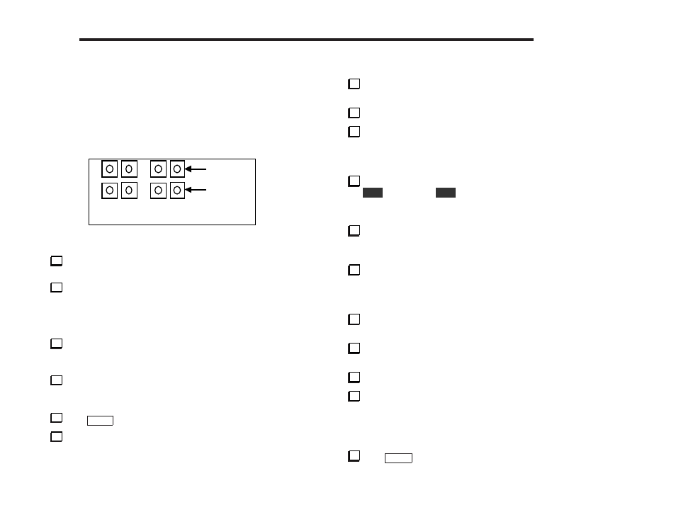
On the Filter board, there are premix filters and RF filters for each
band, as shown in Figure 7-2. Each filter has two slug-tuned
inductors. These filters will be peaked in the following steps.
Premix
RF
Band 1
Band 2
Figure 7-2
Locate the plastic tuning tool. The smaller end of the tool will
be used to adjust the slug-tuned inductors.
While listening to atmospheric noise or a CW signal, peak the
two band-1 Premix inductors, L1 and L2. Do not continue to turn
the slug if it has bottomed-out. Stop when you feel resistance. If
you cannot find a peak for L1 and L2, set them to about the mid-
point of their range for now and go on to the next step.
Peak the two band-1 RF inductors, L5 and L6. If no signals are
heard while peaking either L1/L2 or L5/L6, use a transmitter to
generate a stronger signal, or scramble the settings and try again.
Re-peak L1 and L2, then L5 and L6, until no further
improvement is noted. Once all four inductors have been peaked,
received signals and noise should be quite strong.
Tap
B A N D
twice (quickly) to select band 2.
Switch to an appropriate antenna for this band, if available,
and set the VFO for the mid-point of the band.
While listening to noise or a weak signal, peak the band-2
Premix inductors, L3 and L4.
Peak the two band-2 RF inductors, L7 and L8.
Re-peak L3 and L4, then L7 and L8, until no further
improvement is noted.
Coarse BFO Alignment
The K1 three crystal filter bandwidths are selected by holding
the
X F I L
switch. Hold
X F I L
until you see F L 3 on the LCD.
Note: FL1, 2, and 3 are pre-set to bandwidths of about 800, 400,
and 250 Hz. They can be set up differently using F L x (page 53).
Tune in a moderately-strong signal. Adjust the VFO slowly to
find the pitch where the signal is strongest. At this point, the signal
will be centered in the crystal filter.
Locate the BFO trimmer, C20, near the front edge of the RF
board. Adjust C20 for approximately the desired signal pitch.
Fine BFO Alignment Using the Sidetone Pitch
Select your desired sidetone pitch using the S T P menu entry.
(Many CW operators use 500-600 Hz or lower.) Exit the menu.
Tune in a strong signal, adjusting the VFO slowly until the
signal strength is centered in the filter, as you did above.
Turn on the sidetone again using the S T P menu entry.
Adjust C20 so that the pitch of the received signal matches
your sidetone pitch. This is best done with both the received signal
and sidetone at about the same amplitude. The received signal will
seem to "disappear under" or "merge with" the sidetone when the
pitch is closely matched.
Tap
M E N U
twice to return to normal operation.