Display and control circuits (20-39) – Elecraft K1 User Manual
Page 84
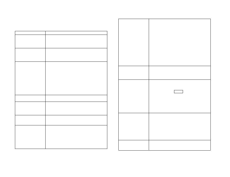
2
Display and Control Circuits (20-39)
Problem
Troubleshooting Steps
20 Regulated
voltage(s) incorrect
DC input voltage must be > 8.5V
Remove all option boards and re-check
If +6V is too low (< 5.7V) go to 22
If +8V is too low (< 7.5V) go to 23
21 General problem
with switches or
potentiometers
Check switch resistance open/closed; check
R14, R15 and RP1
Check resistance of potentiometers; check
related connections to FP-J1
22 +6A or +6B
voltages too low
(< 5.7V)
Remove socketed ICs, front panel board,
filter board, and options individually
Inspect the entire 6A or 6B path on the RF
and Front Panel boards.
Check for regulator ICs installed backwards
Lift the output lead of the affected regulator
and measure the voltage this lead; if the
voltage is still too low, replace the IC
Lift other component leads on the 6V line as
needed to find cause of excess loading
23 +8V too low
(< 7.5V)
Use techniques given for 6V regulators
(above)
24 LCD or LED
problem
LCD in backwards or bent pin; check for
shorts to ground on each LCD pin
MCU pin bent or broken (FP-U1)
LEDs swapped or installed backwards
25 Relay Problem
Relays installed backwards or not soldered
Check relay coil resistance, pins 1 and 10
I/O controller defective or backwards (27)
26 Possible MCU
problem
Check all DC voltages on FP-U1
Remove the Front Panel board and inspect
U1. Make sure it is not backwards, has no
bent pins, and is seated firmly in its socket.
Check oscillator components (X1, C1, C2).
Also see (33) if you suspect an error in a
menu parameter, etc.
27 Filter board not
plugged in, or I/O
controller (FIL-U1)
communication
problem
If you saw the message
E 2 7
, the I/O
controller (IOC, FIL-U1) did not respond to
messages from the main processor (MCU,
FP-U1). Turn power OFF and back ON; if
you hear some relays switching, the IOC may
be OK, and the problem is likely to be with
the AuxBus (29)
If you do not hear any relays switching on
power-up, your IOC (FIL-U1) may be
defective. Inspect FIL-U1 to see if you have
installed it backwards or if any pins are bent.
With power ON, check all voltages
associated with U1. You should see 6V at
pins 1 and 14. See DC voltage table.
28 I/O controller data
error
If you saw the message
E 2 8
, the I/O
controller (IOC, FIL-U1) sent an incorrect
response to the MCU (FP-U1). This may
indicate a firmware incompatibility.
29 AuxBus problem
Try removing each option board
If voltage at pin 13 of the IOC (FIL–U1), the
auxBus line may be shorted
Try tapping the
B A N D
switch quickly while
watching pin 13. It should drop below 6V
briefly if the MCU (FP-U1) is sending a
message to the IOC.
Check the AuxBus signal at the MCU, pin 8
(FP-U1). The voltage should drop below 6V
briefly when the band is changed.
30 EEPROM
write/read test #1
failed
31 EEPROM
write/read test #2
failed
32 EEPROM data
error
If you
E 3 0
,
E 3 1
or
E 3 2
on the LCD, one
of the EEPROM tests has failed. CW
memories cannot be used. Parameters will be
set to defaults, and band 1 will be selected.
Verify that the Filter board is plugged in.
Check all voltages on the EEPROM (FP-U3)
Inspect FP-U3 and surrounding traces
Make sure FP-R16 is installed
33 Configuration data
or menu problem
If a menu parameter is out of range or can’t
be modified, EEPROM may need to be
reinitialized. See page 57 for instructions.