Elecraft K1 User Manual
Page 45
44
E
LECRAFT
Bend the center lead of Q7 slightly away from the side panel,
forming it as shown in Figure 8-3.
Hold the right side panel up to the right edge of the RF board.
Insert Q7's leads into their pads while guiding the panel into
position. Secure the right side panel to the RF board using two
3/16" (4.8 mm) flat-head screws.
Solder and trim the leads of Q7 on the bottom of the board.
Using an ohmmeter on a low resistance scale, check for a
short from Q7's tab to ground. (The tab is connected to the
collector lead.) The metal hardware used to hold Q7 to the side
panel may show low resistance to ground, but the tab should be
floating (> 1 k).
Install 8-pin ICs U8 (SA602
or SA612AN) and U9 (LT1252).
Orient the ICs as indicated by their component outlines.
i
Toroidal transformers T3 and T4 must be wound exactly as
described in the following steps. Recall that transformer windings
are identified by numbered pairs of leads, which correspond to the
numbered PC board pads.
T3 is wound on an FT37-43 core (dark gray), the smaller of
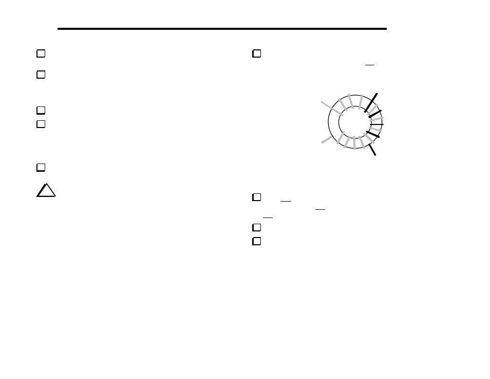
the two cores remaining. Start with the 1-2 winding, which uses 12
turns of red enamel wire (9", 22 cm). See Figure 8-4.
1, RED
2, RED
4, GRN
3, GRN
Figure 8-4
T3's 3–4 winding uses 4 turns of green enamel wire (6", 16
cm). The turns of the 3-4 winding must be tightly interlaced with
the 1-2 winding as shown in Figure 8-4.
Strip and tin T3’s leads.
Install T3 flat against the PC board, to the right of Q6. Pull
the leads taut on the bottom side before soldering.