Preparation for assembly, Overview of the k1 – Elecraft K1 User Manual
Page 7
6
E
LECRAFT
3. Preparation for Assembly
Overview of the K1
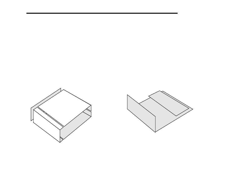
The K1 uses modular design for ease of assembly and
troubleshooting. The chassis is made up of five pieces (Figure 3-1),
any of which can be removed individually. The RF power amplifier
transistor uses the right side panel as a heat sink, so there is no
separate heat sink element. Each side panel includes a 10-32
threaded PEM nut as a mounting point for the KTS1 tilt stand.
Top Cover
Front
Panel
Side
Panel
Bottom
Cover
(Right side panel
not shown)
Figure 3-1
There are three printed circuit boards (PCBs), as shown in
Figure 3-2: Front Panel board, Filter board, and RF board. These
boards plug in together with no wiring, as explained in the next
section. K1 options, such as the KNB1 noise blanker, also plug in
directly. Appendix D shows photographs of each completed PC
board assembly.
Front
Panel
RF
Filter
Figure 3-2
- KX3 Owner's Manual (58 pages)
- KX3 Assembly Manual (47 pages)
- KX3 Assembly Manual Errata (5 pages)
- KX3-2M (30 pages)
- KX3-PCKT (2 pages)
- KX3 Mobile Installation And Operation Guide (17 pages)
- KX3 Guide for Blind Operators (7 pages)
- KX3 Quick Reference (2 pages)
- K3 Programmers Reference (26 pages)
- KX3 Speaker Grille Instructions (9 pages)
- KXFL3 Filter Option (12 pages)
- KXFL3 Filter Option Errata (2 pages)
- KXAT3 (5 pages)
- KXBC3 (13 pages)
- KXPD3 (4 pages)
- Proset Boom Headset (1 page)
- PX3 Owner's Manual (53 pages)
- PX3 Owners Manual Errata (2 pages)
- KXPA100 Manual (55 pages)
- KXPA100 Assembly Manual (27 pages)
- KXPA100 Assembly Errata (1 page)
- KXPA100 Programmers Reference (24 pages)
- KXAT100 Installation Manual (17 pages)
- KX1 Manual (96 pages)
- KXAT1 (12 pages)
- KXPD1 (7 pages)
- KXB30 (8 pages)
- KXB3080 (20 pages)
- K1 1.09 F/W (1 page)
- KNB1 Manual (8 pages)
- KAT1 Manual (15 pages)
- KFL1-2 (2 pages)
- KTS1 (1 page)
- KBT1 Manual (8 pages)
- KBT1 Manual Errata (2 pages)
- K1BKLTKT LCD Mod Kit (6 pages)
- K2 Owner's Manual (171 pages)
- K2 Owner's Manual Errata (1 page)
- K2 PLL (4 pages)
- K2ATOBKIT (15 pages)
- K2ATOBKT (2 pages)
- K2 Keying Modification Instructions (4 pages)
- KPA100 Manual (74 pages)
- KPA100 Shield Upgrade (3 pages)