Elecraft K1 User Manual
Page 25
24
E
LECRAFT
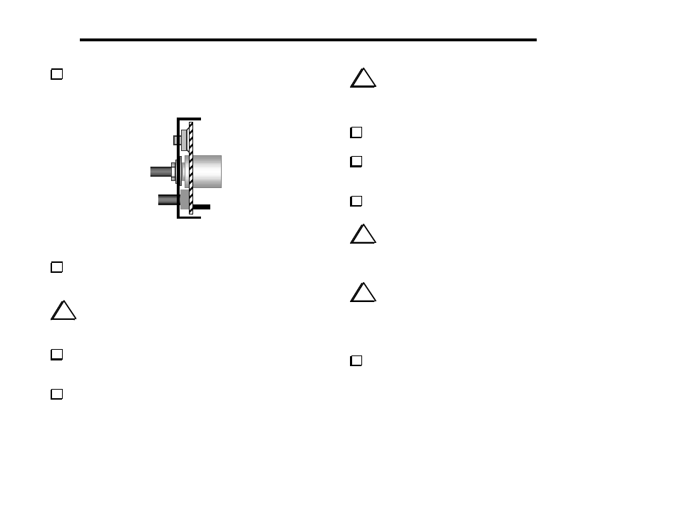
Insert the Front Panel PC board assembly into the front panel
(Figure 5-12). The push-button switch caps should protrude slightly.
Figure 5-12
The 1/4" (6.4 mm) standoff on the PC board should now be
visible through the countersunk panel hole just below R1. Secure the
panel to the standoff with a 3/16" (4.8 mm) flat-head screw.
i
Caution: The 10-turn potentiometer may have a
plastic bushing. In the following step, do not over-tighten
the nut or you may strip the threads.
Use the nut and lock washer supplied with R1 to secure it to
the front panel. It should be just tight enough to keep R1 from
rotating.
Place the large knob on R1's shaft. Push the knob on until it
just touches the bushing. If the knob does not spin freely, move it
out slightly. If the shaft or knob appears to be tilted, the large
nylon washer may not be positioned correctly (behind the panel).
i
The Allen wrenches are located in a small bag with the
MISCELLANEOUS items. These wrenches may have been oiled
during manufacturing. Remove the wrenches and wipe off the oil, if
any, then discard the bag.
Use the larger Allen wrench (5/64" [2 mm]) to tighten the two
set screws on the large knob.
Set the AF GAIN and RIT/XIT potentiometers to midway in
their rotation, and place a small knob on each. Do not push down
hard on the knobs, as this may damage the potentiometers.
Tighten each knob's two set screws using the smaller Allen
wrench (.050" [1.3 mm]). Align the pointers per panel labeling.
i
At this point in the assembly, the push-button switches
may not all protrude an equal distance. The switch height will
become equalized once the front panel assembly is mated to the RF
board in a later step.
i
When you rotate the VFO knob, you may hear a faint
sound produced by the wiper of the 10-turn potentiometer as it
moves across its resistance element. This is normal.
Uninstalled Components
All component locations should now be filled.