Elecraft K1 User Manual
Page 16
E
LECRAFT
15
i
The connectors to be installed in the following steps
must be positioned correctly to avoid intermittent or
unreliable operation.
Before attempting to install multi-pin connectors, review the
information on page 7.
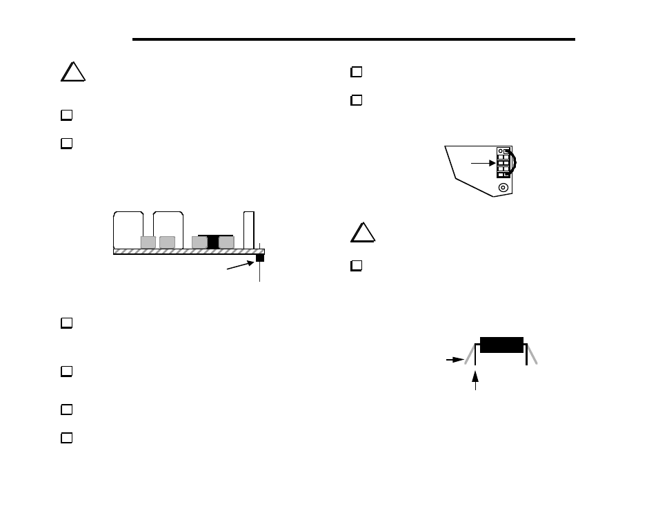
Install an 8-pin male connector (plug) at P1, but do not solder
yet. Figure 4-4 shows P1 as viewed from the left end of the Filter
board. The plastic part of the connector must be on the bottom
side of the board, with the long end of the pins pointed down. The
short pins are inserted into the board.
P1
Figure 4-4
Solder just one of the middle pins of P1, on the top side.
Note: multi-pin connectors have plastic bodies that can melt if too
much heat is applied, causing the pins to be mis-positioned. Limit
soldering time for each pin to 2 to 3 seconds.
Examine the placement of P1 closely. If it is tilted or is not
flat against the board, re-heat the solder while pressing down on the
connector.
Once P1 is in the right position, solder the remaining pins. Do
not trim the leads.
Install P2 and P3 in the same manner as P1. Before soldering,
verify that each connector is flat against the board and not tilted.
Cut a 1" (25 mm) length of insulated hookup wire. Strip about
1/8" (3 mm) of insulation off of each end.
Install this wire between pins 2 and 10 of J2, in the upper right-
hand corner of the board (Figure 4-5). The pins on J2 are counted
from left to right and top to bottom as shown.
J2
1
2
10
9
Figure 4-5
i
Before handling U1 in the next step, touch an unpainted,
grounded metal surface.
Straighten the leads of U1 (PIC16C620) as shown in Figure
4-6. The two rows of pins must be straight and parallel to each
other to establish the proper pin spacing. To straighten the pins,
rest one entire row of pins against a hard, flat surface. Press down
gently on the other row of pins and rock the IC forward to bend the
pins into position as shown below.
Straight
Flared
Figure 4-6