Elecraft K1 User Manual
Page 28
E
LECRAFT
27
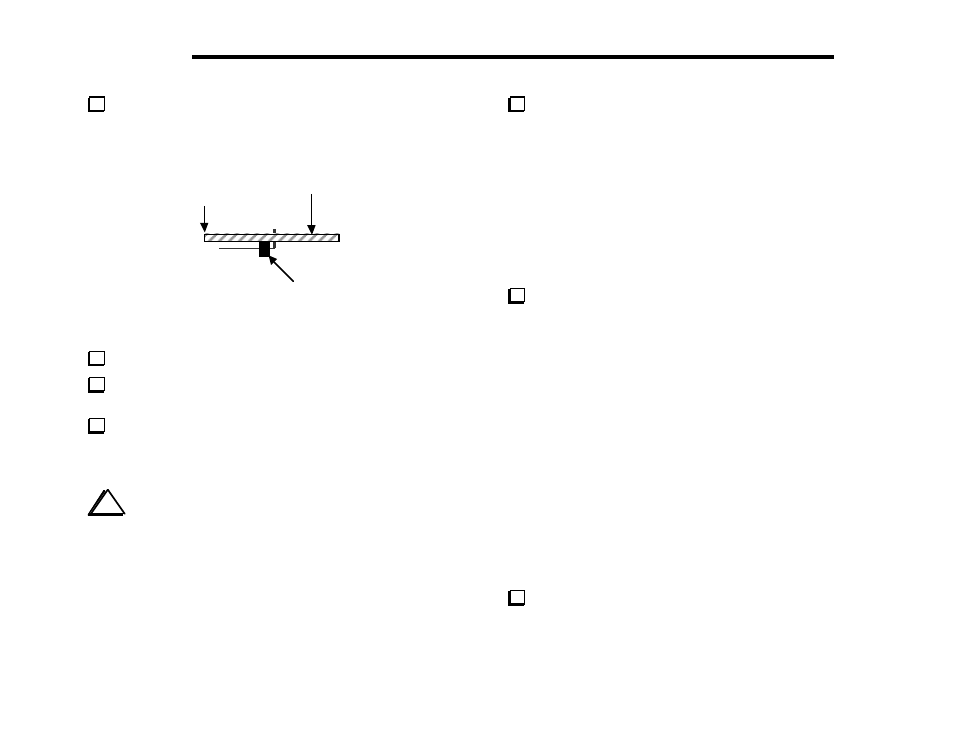
Position 20-pin male right-angle connector P1 on the bottom
of the RF board (Figure 6-5), but do not solder yet. Review Figure
3-3 for correct placement. The short ends of the bent pins are
inserted into the holes, and the long ends are parallel to the board.
Front edge
P1
Top of board
Figure 6-5
Solder just the two end pins of P1.
Make sure that the front-panel assembly can be plugged into
P1 as shown in Figure 3-3. Then unplug the front panel assembly.
Look closely at P1 to make sure that its plastic support is
pressed down as far as it will go, and that the pins are parallel to the
board. If not, re-heat the soldered ends while pressing it into place.
Once it is seated properly, solder the remaining pins.
i
In the steps that follow, you'll be installing larger groups of
components. When working from a long list, install all of the items
on one line before moving on to the next. Arrows (
⇒
) appear in
the list to remind you of this order. In general, assembly proceeds
from left to right across the board.
Note: All components mounted in the T-R switch and transmitter
areas must be kept as low-profile as possible since the Filter board
will be plugged in directly above.
Install the resistors listed below. R23 is at the left-front edge.
__ R23, 1.5 Ω (BRN-GRN-GOLD)
⇒
__ R7, 680 (BLUE_GRAY-BRN)
__ R21, 2.7 k (RED-VIO-RED)
__ R13, 2.2 M (RED-RED-GRN)
__ R2, 100 k (BRN-BLK-YEL)
__ R16, 75 (VIO-GRN-BLK)
__ R17, 120 (BRN-RED-BRN)
__ R18, 75 (VIO-GRN-BLK)
__ R14, 2.7 k (RED-VIO-RED)
__ R1, 1.8 k (BRN-GRAY-RED)
These resistors start on the left edge of the board near J6:
__ R19, 39 k (ORG-WHT-ORG)
⇒
__ R20, 20 k (RED-BLK-ORG)
__ R9, 2.7 k (RED-VIO-RED)
__ R26, 1.8 k (BRN-GRAY-RED)
__ R34, 100 k (BRN-BLK_YEL) (at the back-right edge near J8)
The following capacitors are all of the disc or monolithic
type. Start with C26, which is on the left edge close to J6.
Note: C65 (22 pF) may be labeled "220J" (see top of page 9).
__ C26, 39 (39)
⇒
__ C27, 39 (39)
⇒
__ C42, 220 (221)
__ C41, .047 (473)
__ C30, .047 (473)
__ C40, .01 (103)
__ C25, .01 (103)
__ C7, 39 (39)
__ C4, .01 (103)
__ C6, .01 (103)
__ C69, 220 (221)
__ C72, .01 (103)
__ C18, .01 (103)
__ C74, .01 (103)
__ C73, 0.1 (104)
__ C64, .01 (103)
__ C68, 0.1 (104)
__ C17, .01 (103)
__ C32, .047 (473)
__ C70, 0.1 (104)
__ C71, 0.1 (104)
__ C23, .01 (103)
__ C75, .01 (103)
__ C63, 330 (331)
__ C65, 22 (22, 220J)
__ C61, .047 (473)
__ C24, .047 (473)
__ C19, .001 (102)
__ C66, .01 (103)
__ C21, .01 (103)
__ C22, .001 (102)
__ C39, 220 (221)
__ C37, .01 (103)
__ C38, 220 (221)
__ C36, .01 (103)
__ C34, 0.1 (104)
__ C28 and __ C29, .001 (102)
(back-left corner of the board)
__ C49 and __ C48, .01 (103)
(back-right corner)
__ C45, .01 (103) (near J4, which is on the back edge)
1200-pF polystyrene capacitor C11 (labeled “1200J”) has
axial leads, like a resistor. Note: the kit also includes a 120 pF
polystyrene ("120J"). Install C11 in the VFO area of the board,
near J6. Limit soldering time to 2-3 seconds.