Elecraft K1 User Manual
Page 34
E
LECRAFT
33
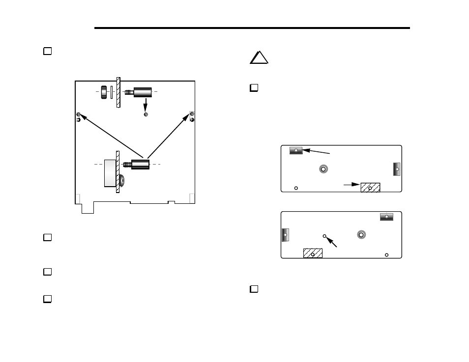
On the top side of the RF board, locate the hole identified as
(A) in Figure 6-9. (The label "S1" appears near the hole.)
J6
(A)
(B)
(B)
Figure 6-9
Install a 7/16" (11 mm) hex male-female standoff on the top
of the board at location (A) as shown. Use an internal-tooth lock
washer and 4-40 nut on the bottom. Do not over-tighten the
hardware; the standoff threads can be easily stripped.
Install 7/16" (11 mm) hex male-female standoffs at the two
locations identified as (B) in Figure 6-9, replacing the existing
3/16" pan-head screws. Do not use any lock washers.
Temporarily place the Filter board assembly on top of the
three standoffs just installed. If the standoffs are in the correct
positions, they will be visible through their holes in the Filter board.
i
When working with the side panels in the following steps,
place a soft cloth on your work surface to protect the paint. (A
clean anti-static mat will also suffice.)
Locate the two side panels and arrange them as shown in
Figure 6-10, with the inside surfaces facing up. The right side can be
identified by the presence of an extra hole as shown. The
illustration also shows where 2-D fasteners will be installed, as well
as the areas which were masked during painting.
Right side, inside surface
Left side, inside surface
Extra hole
2-D Fastener
Masked area
Figure 6-10
Remove any masking tape from the panels using the same
technique described on page 23, taking care not to scratch the outer
surfaces.