1 tare (pin 1), 2 peak (pin 2), 3 valley (pin 3) – Cooper Instruments & Systems DFI INFINITY B Ultra High Performance Digital Force Indicator User Manual
Page 75: 4 swlin2 (pin 4), 5 external reset (pin 5), 6 no connection (pin 6), 7 digital return (pin 7)
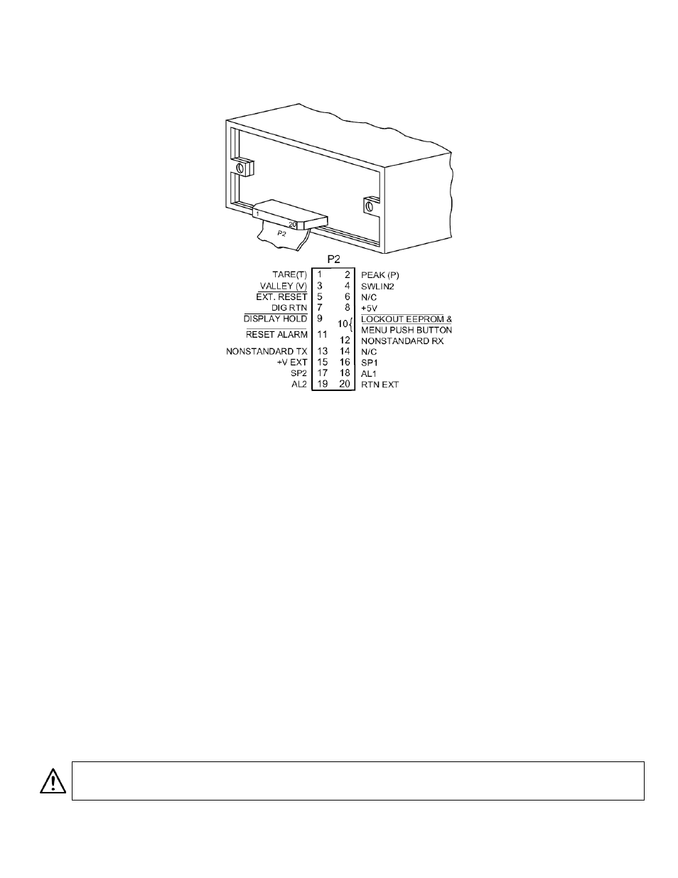
The meter case label gives the names (abbreviated functions) of each of the twenty pins of P2, the center-bottom
connector. Refer to Figure 30-1.
Figure 30-1. Connector Label Detail
31.1 TARE (PIN 1)
Tare is available when P2-1 and P2-4 are connected to a momentary contact switch. This feature allows you to
automatically zero your meter when the switch is activated. Tare is not available for temperature meters.
31.2 PEAK (PIN 2)
When this is connected to P2-4 by an external switch, the meter displays the stored PEAK (“HI RDG”) value rather than
the current reading. The display flashes to distinguish this value.
31.3 VALLEY (PIN 3)
When this is connected to P2-4 by an external switch, the meter displays the stored valley (“LO RDG”) value rather than
the current reading. The display flashes to distinguish this value.
31.4 SWLIN2 (PIN 4)
Completes the circuit for any of the above three signals.
31.5 EXTERNAL RESET (PIN 5)
Connecting this to ground (P2-7) causes a “HARD” RESET (when you see “RESET2” on the display).
31.6 NO CONNECTION (PIN 6)
31.7 DIGITAL RETURN (PIN 7)
This is a non-isolated return to be used for the digital controls provided on this P2 connector.
WARNING: THIS METER RETURN IS NOT ISOLATED FROM THE SIGNAL INPUT AND SHOULD NOT BE
CONNECTED TO EXTERNALLY-GROUNDED DEVICES UNLESS ISOLATION IS PROVIDED EITHER AT THE
SIGNAL INPUT OR AT THIS EXTERNAL-LOGIC CONNECTION.
CF 156
70
M2544/N/0505