6 connecting main ac power – Cooper Instruments & Systems DFI INFINITY B Ultra High Performance Digital Force Indicator User Manual
Page 31
FRANCE
GERMANY
T/C
TYPE
WIRE COLORS
WIRE COLORS
+ LEAD
- LEAD
+ LEAD
- LEAD
J Yellow Black Red Blue
K Yellow Purple Red Green
T Yellow Blue Red Brown
E Yellow Purple Red Black
N
No Standard-See USA No Standard-See USA
R Yellow Green Red White
S Yellow Green Red White
B Use
Copper
Wire Red Gray
DIN
J
Red Blue Red Blue
JAPAN UNITED
KINGDOM
T/C
TYPE
WIRE COLORS
WIRE COLORS
+ LEAD
- LEAD
+ LEAD
- LEAD
J Red White Yellow Blue
K Red White Brown Blue
T Red White White Blue
E Red White Brown Blue
N
No Standard-See USA
No Standard-See USA
R Red White White Blue
S Red White White Blue
B
Red
Gray
No Standard-See USA
DIN J
Red
Blue
Red
Blue
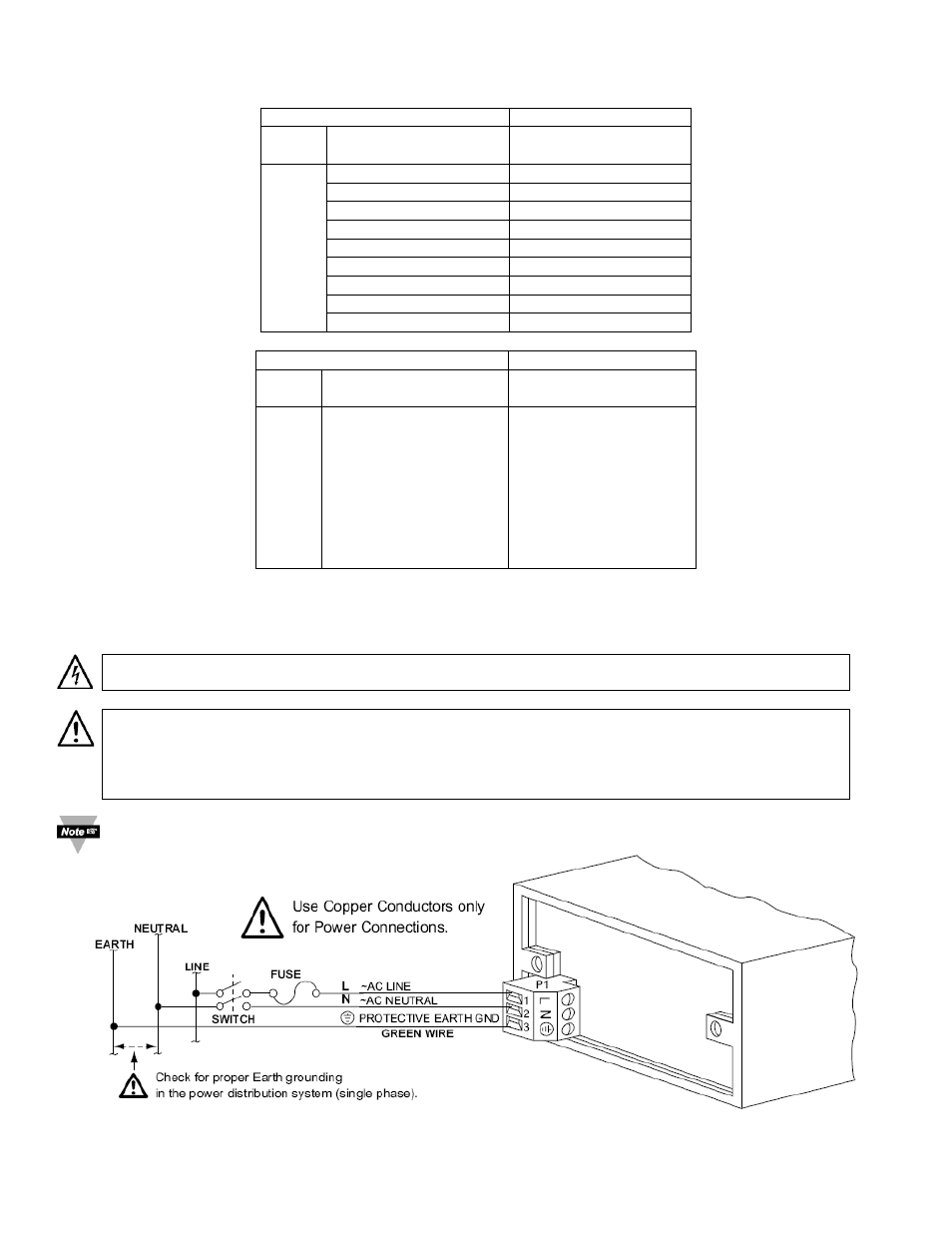
7.6 Connecting Main AC Power
Connect the AC main power connections as shown in Figure 7-22.
CAUTION: As mentioned in Section 3.1, the meter has no power ON/OFF switch. The meter will be ON
when power is applied.
WARNING: Do not connect ac power to your meter until you have completed all input and output
connections. Failure to do so may result in injury! This device must only be installed electrically by
specially trained electrician with corresponding qualifications. The main power input to the unit as well as
the AC input signal to be measured must agree with the wiring instruction. The meter is factory set to the
power specified by the customer at the time of ordering. The voltage is printed on the Product ID Label.
Earth ground MUST be connected to the same earth ground used by the signal source, in order to achieve
published stability and accuracy specifications.
CF 156
26
M2544/N/0505