Rockwell Automation GV3000/SE AC Drive 1-20HP, 230VAC Ver. 6.04 Hdwe Ref, Install, Troubleshooting User Manual
Page 52
7-2
GV3000/SE 230 VAC 1-20 HP Drive, Hardware Reference Version 6.04
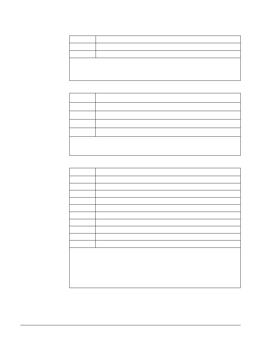
Table 7.5 – Digital Input Connections (Terminals 16-25)
Terminal #
16
17
18
19
20
21
22
23
24
25
Signal
+24 VDC (Current Limited) (For remote control digital inputs only)
Digital Input 8 (Remote/Local) - Programmable
Digital Input 7 (Ramp 1/Ramp 2) - Programmable
Digital Input 6 (Forward/Reverse) - Programmable
Function Loss
Run/Jog
Reset
Stop
Start
+24 VDC Common
Notes: When a user-installed function loss input, a coast-to-stop pushbutton, or another
external interlock is installed, the factory-installed jumper connecting terminals 16 and 20
must be removed so that a contact, when open, will stop the drive.
Terminals 17, 18, and 19 (remote control inputs 8, 7, and 6) are programmed using
parameters P.007, P.008, and P.031 through P.038. Factory default settings are shown
here in parentheses. Refer to the GV3000/SE Software Start-Up and Reference manual
for more information.
Table 7.3 – Analog Output Connections (Terminals 10 and 11)
Terminal #
10
11
Signal
Analog Meter Output
Regulator Common
Notes: The output of this terminal is either 0-10 VDC or 4-20 mA as determined by the
setting of jumper J17 on the Regulator board. The analog output must also be
programmed via parameter P.012 for an indication of speed and direction or percent of
torque.
Table 7.4 – Analog Speed/Torque Reference Connections (Terminals 12-15)
Terminal #
12
13
14
15
Signal
Isolated Reference Voltage
VDC Speed/Torque Reference
mA Speed/Torque Reference
Isolated Reference Common
Notes: The analog speed/torque (P.008/U.000) reference is either +/–10 VDC or
+/–20 mA, as determined by the setting of jumper J4 on the Regulator board. The analog
reference can be adjusted using parameters P.009, P.010, and P.011.