Rockwell Automation GV3000/SE AC Drive 1-20HP, 230VAC Ver. 6.04 Hdwe Ref, Install, Troubleshooting User Manual
Page 23
2-9
About the Drive
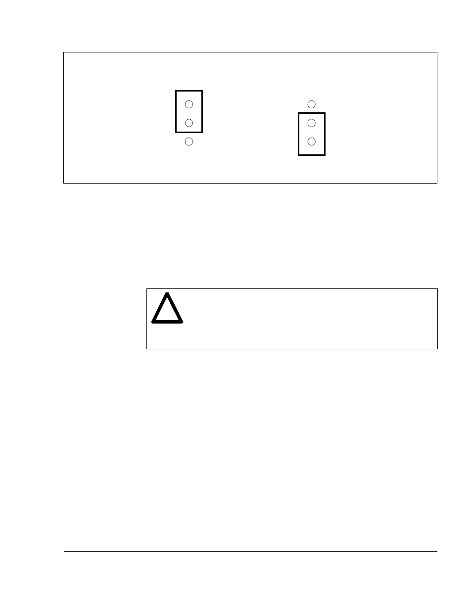
Figure 2.6 – Jumper J4 Settings for Analog Input Speed Reference
2.4.1.2 Analog Output Jumper (J17)
Jumper J17 is the analog output jumper. This jumper selects either a 0-10 VDC or
4-20 mA scaled signal output that is programmable for either speed or torque,
parameter P.012. The jumper only selects a 0-10 VDC source voltage or 4-20 mA
sink current to represent speed or torque. Note that the 4-20 mA current selection
requires a power supply for operation as shown in table 7.8, terminals 10 and 11.
Use the following procedure to set jumper J17:
ATTENTION: DC bus capacitors retain hazardous voltages after input
power has been disconnected. After disconnecting input power, wait
five (5) minutes for the DC bus capacitors to discharge and then check
the voltage with a voltmeter to ensure the DC bus capacitors are
discharged before touching any internal components. Failure to observe
this precaution could result in severe bodily injury or loss of life.
Step 1. Turn off input power to the drive and wait five minutes.
Step 2. Remove the cover from the drive by unscrewing the two attaching screws.
Step 3. Verify that the DC bus voltage is zero by following the procedure in section
9.3.
Step 4. Locate jumper J17 on the Regulator board. Refer to figure 2.5.
Step 5. Locate pin 1 on jumper J17. Move the jumper to the desired setting as
shown in figure 2.7.
Step 6. Reattach the cover.
Step 7. Reapply input power.
Step 8. Verify that parameter P.012 is set correctly for either speed or current.
!
10 VDC
J4
0-20 mA
J4
Voltage Input Option
Pins 2-3
Current Input Option
Pins 1-2
(default)