Hapter, Wiring the regulator board terminal strip – Rockwell Automation GV3000/SE AC Drive 1-20HP, 230VAC Ver. 6.04 Hdwe Ref, Install, Troubleshooting User Manual
Page 51
7-1
Wiring the Regulator Board Terminal Strip
C
HAPTER
7
Wiring the Regulator Board
Terminal Strip
This chapter describes how to wire the Regulator board terminal strip for stop,
encoder feedback, and remote control signals.
The signals available through the terminal strip are shown in tables 7.1 to 7.7 and
figures 7.1 and 7.2. Table 7.8 provides additional information.
Note that when the Control Source parameter (P.000) is set to remote (rE), the drive
will be controlled by the signals connected to the terminal strip. Refer to the
GV3000/SE Software Start-Up and Reference manual for more information on how
parameter P.000 is used to specify where the drive is controlled from.
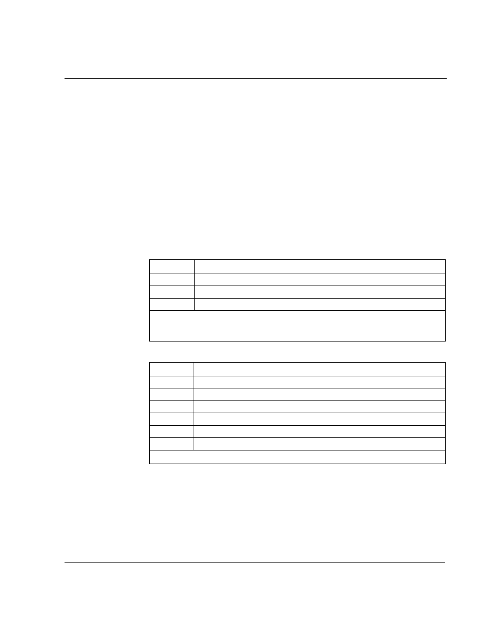
Table 7.1 – RS-232 Connections (Terminals 1-3)
Terminal #
1
2
3
Signal
Transmit (Tx)
Receive (Rx)
Regulator Common
Notes: The RS-232 terminals should only be used when the RS-232 communication port
(J8) or an Operator Interface Module (OIM) are not being used, as all three devices use
the same transmit/receive lines.
Table 7.2 – Encoder Connections (Terminals 4-9)
Terminal #
4
5
6
7
8
9
Signal
+15 VDC
Phase A
Phase A Not
Phase B
Phase B Not
Regulator Common
Notes: An encoder feedback device must be installed if FVC regulation is used.