Rockwell Automation Liqui-Flo 1.5 General Purpose and Vector Duty User Manual
Page 126
5-12
LiquiFlo 1.5 AC Drive, Software Reference Version 1.2
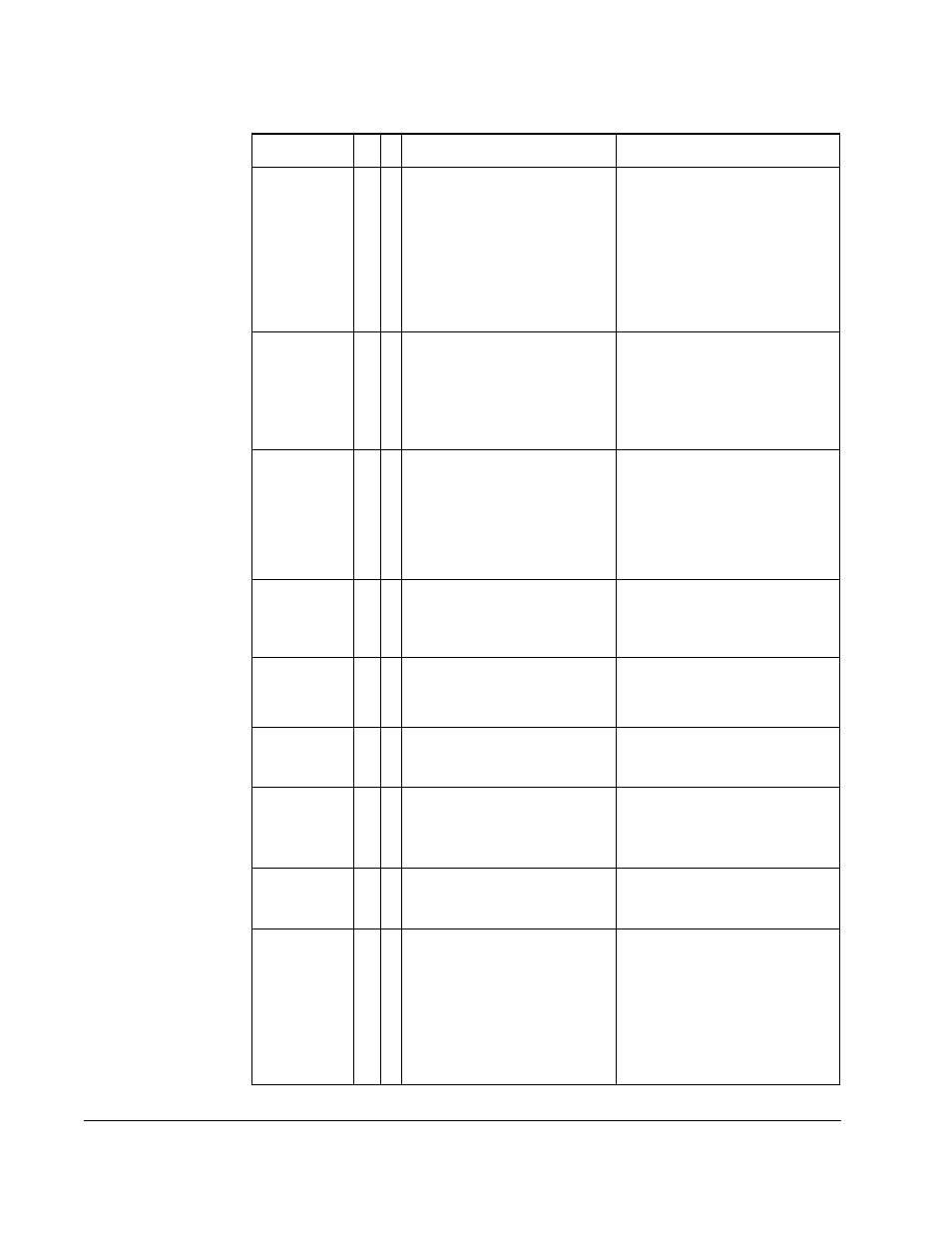
Port 1-6 Net
Loss
71-
76
The network card connected
to DPI port stopped
communicating.
The fault code indicates the
offending port number (71 =
port 1, etc.)
1.
Check communication
adapter board for proper
connection to external
network.
2.
Check external wiring to
adapter on port.
3.
Verify external network
fault.
Power Loss
3
➀
➂
DC bus voltage remained
below 85% of nominal for
longer than Power Loss Time
(185).
Enable/disable with Fault
Config 1 (238).
Monitor the incoming AC line
for low voltage or line power
interruption.
Power Unit
70
One or more of the output
transistors were operating in
the active region instead of
desaturation. This can be
caused by excessive
transistor current or
insufficient base drive voltage.
1.
Check for damaged output
transistors.
2.
Replace drive.
Pwr Brd
Chksum1
104
The checksum read from the
EEPROM does not match the
checksum calculated from the
EEPROM data.
Clear the fault or cycle power to
the drive.
Pwr Brd
Chksum2
105
➁
The checksum read from the
board does not match the
checksum calculated.
1.
Cycle power to the drive.
2.
If problem persists, replace
drive.
Replaced
MCB-PB
107
➁
Main Control board was
replaced and parameters
were not programmed.
1.
Restore defaults.
2.
Reprogram parameters.
Shear Pin
63
➂
Programmed Current Lmt Val
(148) has been exceeded.
Enabled/disable with Fault
Config 1 (238).
Check load requirements and
Current Lmt Val (148) setting.
SW
OverCurrent
36
➀
The drive output current has
exceeded the software
current.
Check for excess load,
improper DC boost setting. DC
brake volts set too high.
Trnsistr
OvrTemp
9
➀
Output transistors have
exceeded their maximum
operating temperature.
1.
Check for blocked or dirty
heat sink fins. Verify that
ambient temperature has
not exceeded 40
°
C (104
°
F)
for NEMA Type 1 installations
or 50°C (122°F) for Open type
installations.
2.
Check fan.
Table 5.6 – Fault Descriptions and Corrective Actions (Continued)
Fault
No.
Ty
p
e
Description
Action