1 alarm descriptions – Rockwell Automation Liqui-Flo 1.5 General Purpose and Vector Duty User Manual
Page 118
5-4
LiquiFlo 1.5 AC Drive, Software Reference Version 1.2
5.3.1 Alarm Descriptions
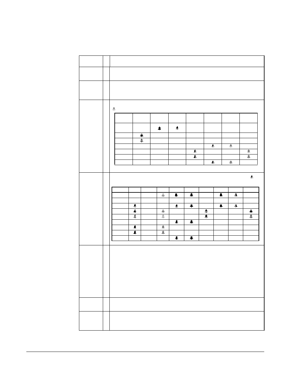
Table 5.3 – Alarm Descriptions
Alarm
Ty
p
e
Description
Analog In
Loss
➀
An analog input is configured for alarm on signal loss and signal loss
has occurred.
Bipolar
Conflict
➁
Parameter 190 (Direction Mode) is set to Bipolar or Reverse Dis and
one of more of the following digital input functions is configured:
Fwd/Rev, Run Fwd, Run Rev, Jog Fwd, or Jog Rev.
Dig In
ConflictA
➁
Digital input functions are in conflict. Combinations marked with a
will cause an alarm.
Dig In
ConflictB
➁
Digital input functions are in conflict. Combinations marked with a
will
cause an alarm.
Dig In
ConflictC
➁
More than one physical input has been configured to the same input
function. Multiple configurations are not allowed for the following input
functions:
DigIn Bad
Value
➁
Unsupported function selected in Digital In”x” Sel parameters
(361-366).
Drive OL
Level 1
➀
The calculated IGBT temperature requires a reduction in PWM carrier
frequency. If Drive OL Mode (150) is disabled and the load is not
reduced, an overload fault will eventually occur.
Acc2 /
Dec2
Accel 2
Decel 2
Jog
Jog Fwd
Jog Rev
Fwd / Rev
Acc2 /
Dec2
Accel 2
Decel 2
Jog
Jog Fwd
Jog Rev
Fwd / Rev
Start
Stop–CF
Run
Run Fwd Run Rev
Jog
Jog Fwd Jog Rev Fwd/Rev
Start
Stop–CF
Run
Run Fwd
Run Rev
Jog
Jog Fwd
Jog Rev
Fwd / Rev
Forward/Reverse
Run Reverse
Bus Regulation Mode B
Speed Select 1
Jog Forward
Acc2 / Dec2
Speed Select 2
Jog Reverse
Accel 2
Speed Select 3
OIM Control
Decel 2
Run Forward
Stop Mode B
Run