Rockwell Automation Liqui-Flo 1.5 General Purpose and Vector Duty User Manual
Page 119
Troubleshooting the Drive
5-5
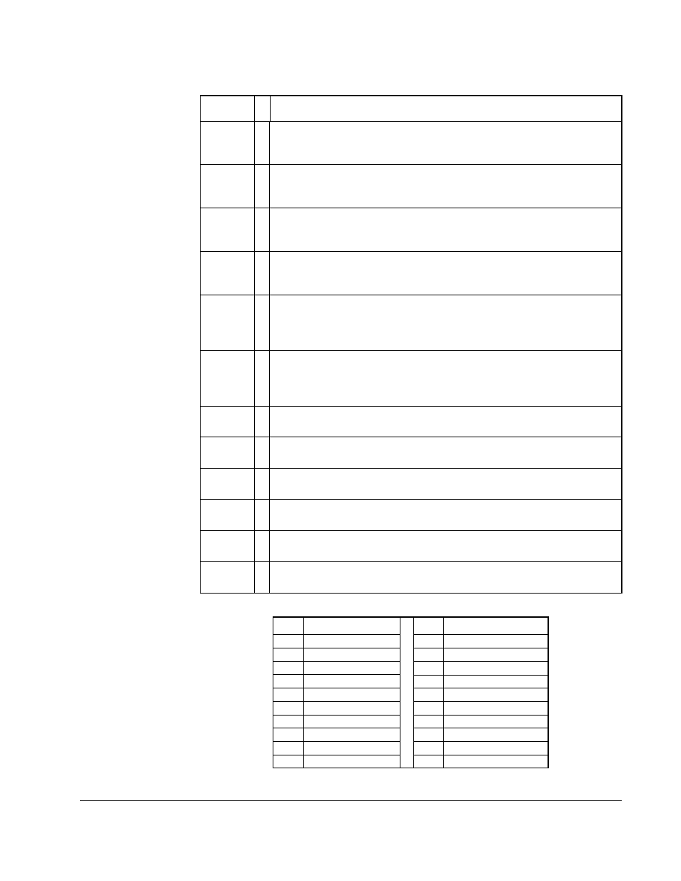
Drive OL
Level 2
➀
The calculated IGBT temperature requires a reduction in Current Limit.
If Drive OL Mode (150) is disabled and the load is not reduced, an
overload fault will eventually occur.
Flux
Amps Ref
Rang
➁
Result of autotune procedure (61).
IntDBRes
OvrHeat
➀
The drive has temporarily disabled the dynamic braking regulator
because the resistor temperature has exceeded a predetermined
value.
IR Volts
Range
➁
The drive autotuning default is Calculate and the value calculated for IR
Drop Volts is not in the range of acceptable values. This alarm should
clear when all motor nameplate data is properly entered.
MaxFreq
Conflict
➁
The sum of Maximum Speed (82) and Overspeed Limit (83) exceeds
Maximum Freq (55). Raise Maximum Freq (55) or lower Maximum
Speed (82) and/or Overspeed Limit (83) so that the sum is less than or
equal to Maximum Freq (55).
Motor
Type Cflct
➁
Motor Type (90) has been set to Sync Prm Mag or Sync Reluc, and one
or more DC functions (for example, DC Boost, DC Brake, etc.) have
been activated. DC injection functions are imcompatible with
synchronous motors and may demagnetize them.
NP Hz
Conflict
➁
Fan/pump mode is selected in Torq Perf Mode (53), and the ratio of
Motor NP Hertz (43) to Maximum Freq (55) is greater than 26.
Power
Loss
➀
Drive has sensed a power line loss.
Prechrg
Actv
➀
Drive is in the initial DC bus precharge state.
Speed
Ref Cflct
➁
Speed Ref x Sel or PI Reference Sel is set to “Reserved”.
Under-
Voltage
➀
The bus voltage has dropped below a predetermined value.
VHz Neg
Slope
➁
Custom V/Hz mode has been selected in Torq Perf Mode (53) and the
V/Hz slope is negative.
Table 5.4 – Alarm Names Cross-Referenced by Alarm Numbers
No.
1
1
Alarm numbers not listed are reserved for future use.
Alarm
No.
1
Alarm
1
Precharge Active
20
Bipolar Conflict
2
UnderVoltage
21
Motor Type Conflict
3
Power Loss
22
NP Hz Conflict
5
Analog In Loss
23
MaxFreq Conflict
6
IntDBRes OvrHeat
24
VHz Neg Slope
8
Drive OL Level 1
25
IR Volts Range
9
Drive OL Level 2
26
FluxAmps Ref Rang
17
Dig In ConflictA
27
Speed Ref Cflct
18
Dig In ConflictB
30
DigIn Bad Value
19
Dig In ConflictC
Table 5.3 – Alarm Descriptions (Continued)
Alarm
Ty
p
e
Description