Rs-485 interface – Rockwell Automation 2755-DM9, -DM9E High Speed Decoder User Manual
Page 87
Chapter 6
Communicating With a Host
6–5
Note: We recommend that you terminate the RS-422 lines if excessive noise
occurs on long RS-422 communication links.
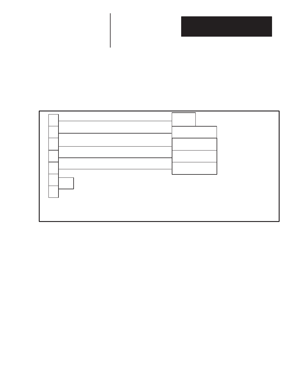
Refer to Figure 6.3 for an illustration of how to connect a host device to the
decoder using the RS-422 interface.
Figure 6.3
Communications With RS-422 Host Device
1
14
15
RS-422 + Receive
CHASSIS GROUND
16
Chassis
Ground
17
18
19
B RS-422 + Send Data (SD)
A RS-422 - Send Data (SD)
Host Device
Exact pin designations depend on
specific host device used.
RS-422 - Receive
RS-422 - Send
A’ RS-422 - Receive Data (RD)
B’ RS-422 + Receive Data (RD)
RS-422 + Send
RS-422 Line Termination
Cable
:
Use shielded, twisted pair
cables. Belden 9512 or
equivalent.
HOST Port on Decoder
Note:
Connect shield to shell of HOST
port connector.
The RS-485 interface provides the ability to multi-drop up to 31 decoders
(from each port) in a communications network using the Catalog No.
2760-RB Flexible Interface Module. As shown in Figure 6.4, the RS-485
interface uses pins 14 (+ Transmit/Receive) and 15 (- Transmit/Receive). If
the decoder is on either of the ends (last drop) in a multi-drop network, you
must enable the termination network (120 ohm resistor in series with a 0.01
microfarad capacitor) by connecting pins #12 and #13 together. Otherwise,
leave pins #12 and #13 open.
Note: Only one of the devices in a multi-drop network must have the cable
shield connected to chassis ground.
Refer to Figure 6.4 for an illustration of how to connect the decoder to an
RS-485 network.
RS-485 Interface