Rockwell Automation 2755-DM9, -DM9E High Speed Decoder User Manual
Page 122
Chapter 8
Host Commands Using the RS-485 Interface
8–10
the decoder’s memory where the host can write data (addresses are provided
in hexadecimal):
1) Configuration Block- Address 400 to 5FF. Refer to Appendix D for
addresses of specific configuration data.
2) Command Area- 600 to 6FF. Writing to the command area will initiate a
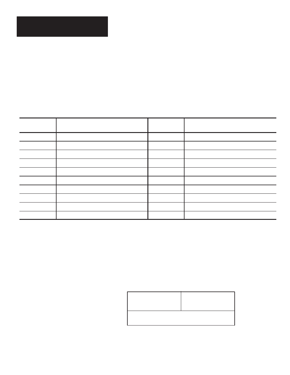
command. Table 8.C lists the commands that can be initiated.
Address
(Hex)
Function
Address
(Hex)
Function
600
Clear Package Counter.
630
Clear All Match Counters.
604
Clear Output Counter 1.
631
Clear All Counters.
608
Clear Output Counter 2.
632
Save Configuration to EEPROM.
60C
Clear Output Counter 3.
633
Set Configuration to Default Values.
610
Clear Output Counter 4.
634
Start Scan Trigger.
614
Clear Output Counter 5.
635
Stop Scan Trigger.
618
Clear Output Counter 6.
636
Flush Host Buffer.
61C
Clear Output Counter 7.
637
Restart.
620
Clear Output Counter 8.
640
Repeat Read (See page 8-13).
624
Clear No-Read Counter
.
641
Cancel Repeat Read (See page 8-13).
DATA (Bytes 6 through 127)- These bytes contain the data that is to be
written into memory (up to 122 bytes).
Unprotected Write Reply Format
The decoder’s reply to a write command has the following structure:
UNPROTECTED WRITE REPLY
STATUS
01001000
TRANSACTION WORD
HI Byte
LOW Byte
The following are descriptions of each byte in the write reply message:
REPLY (Byte O)- The command reply byte has the following structure.