M0:e.1 setup and control word, M0:e.1 setup and control word -25 – Rockwell Automation 1746-HSCE,D17466.5 High-Speed Counter Module User Manual
Page 85
Publication 1746-UM006B-EN-P - August 2005
Configuration and Programming 4-25
M0:e.0 Bits 0 through 7 - Output Source Select (Dynamic)
Bits 0, 1, 2, and 3 represent the Physical Outputs. Bits 4, 5, 6, and 7
represent the Soft Outputs.
The status of these bits determines whether an output is controlled by
the module (when the Function Control bit is set to 1), or by the user
program.
A logic 0 in any of these positions means that the corresponding
output is under module control. A logic 1 means that the
corresponding output is under user program control (refer to O:e.0
Direct Outputs (Dynamic) on page 4-36.
The Output Source Select bit values are dynamic and can be changed
by the user program at any time.
M0:e.0 Bits 8 through 15
Bits 8 through 15 are reserved and must be reset to 0.
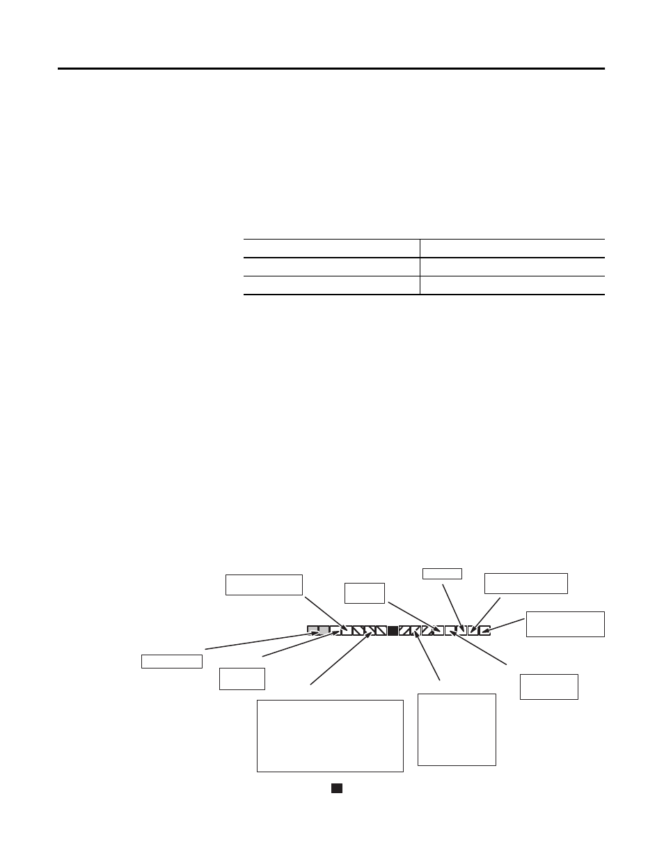
M0:e.1 Setup and Control Word
Output Source Select (bits 4-7)
Output Status
0
output is under module control
1
output is under user program control
M0:e.1
Sequencer Reset
0
0 = No Change
1 = Sequencer Reset
10 = Sequencer
0 = Linear
1 = Ring
0 = Disable Counter
1 = Enable Counter
R
0 = Increment
1 = Decrement
Setup and Control Word, Word 1
Enable Outputs
Counter Hold
Bit Number (decimal)
15 14 13 12 11 10 9
8
7
6
5
4
3
2
1
Soft Reset
Reset Mode
Up/Down Count Direction
Input T
ype
Function Control
Counter T
ype
Operating Mode
000 = No reset
001 = Z
010 = LS
011 = LS and Z
100 = SR
101 = SR and Z
110 = SR and LS
111 = SR, LS, and Z
0 = False
1 = True
1 = Hold
0 = Outputs OFF
1 = Outputs enabled
R
R
= Reserved, must be reset to 0
000 = Invalid
001 = Invalid
010 = Pulse & Direction/External Control
011 = Pulse & Direction/Internal Control
100 = Quadrature Encoder x1
101 = Quadrature Encoder x2
110 = Quadrature Encoder x4
111 = Up / Down Pulse Inputs