Rockwell Automation 1746-HSCE,D17466.5 High-Speed Counter Module User Manual
Page 14
Publication 1746-UM006B-EN-P - August 2005
1-2 Module Overview
Module operation is determined by selections made in the Setup and
Control Word (M0:e.1). Setting the Function Control bit to 1 triggers
the module to start the proper pulse counter, rate measurement, and
output control functions. Many parameters are dynamic and can be
changed without disrupting counter operation.
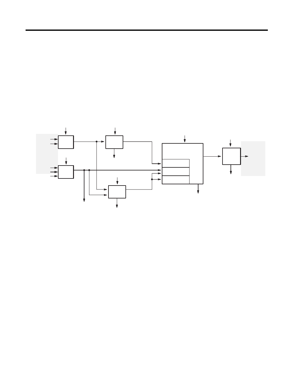
A block diagram of the module is shown below. Inputs from the
terminal block enter the diagram at the left, outputs to the terminal
block exit at the right. M0 and Output file parameters from the SLC
enter the logic blocks from the top. Input file data to the SLC exit the
logic blocks from the bottom.
Input
Logic
A
B
Counter Input
Parameters
Pulse
Counter
Pulse Counter Parameters
Pulse and Direction
Operating Mode Logic
Operating Mode Parameters
Range
Sequencer
Rate
Accumulated Count
Rate
Counter
Rate Period Parameters
Pulse
Counter
Inputs
Reset
Logic
Z
LS
Reset Parameters
LS Filter (JW1)
Reset Condition
Reset
Input
Bit
Rate
Counter
Inputs
Rate Measurement
Operating
Mode
Inputs
Operating
Mode
Outputs
Output
Control
Logic
Output Control
Parameters
Output
Status
Inputs
From Terminal Block
To
Terminal Block
4
Physical
Outputs
Counter Input Parameters
Input Type (M0:e.1/9–11)
Up/Down Count Direction (M0:e.1/3)
–d
Reset Parameters
Soft Reset bit (M0:e.1/4)
–d
Reset Mode (M0:e.1/5–7)
Rate Period Parameters
Rate Period (M0:e.9/0–7 or M0:e.16/0–7)
–d
Operating Mode Parameters
Operating Mode (M0:e.1/14–15)
Function Control Bit (M0:e.1/12)
Range Definitions:
Range Starting Values (M0:e.10 – 33)
–d
Range Ending Values (M0:e.10 – 33)
–d
Range Outputs (M0:e.3 – 8)
–d
Valid Ranges (M0:e.2)
–d
Sequencer Definitions:
Valid Steps (M0:e.2 and M0:e.3/0–7)
–d
Step Presets (M0:e.17 – 40)
–d
Step Outputs (M0:e.4 – 15)
–d
Initial Outputs (M0:e.3/8–15)
–d
Sequencer Reset (M0:e.1/0)
–d
Pulse Counter Parameters
Reset Value (M0:e.34 or M0:e.41)
–d
Maximum Count Value (M0:e.34 or M0:e.41)
Counter Hold bit (M0:e.1/2)
–d
Counter Type bit (M0:e.1/13)
Output Control Parameters
Direct Outputs (O:e.0/0–7)
–d
Output Source Select (M0:e.0/0–7)
–d
Enable Outputs bit (M0:e.1/1)
–d
Rate Counter Inputs
Rate Valid (I:e.0/3)
Rate Counter Overflow (I:e.0/4)
Rate Measurement Overflow (I:e.0/5)
Zero Rate Period Count (I:e.0/2)
Rate Period Count (I:e.2)
Rate Measurement (I:e.3)
Pulse Counter Inputs
Accumulated Count (I:e.1)
Overflow/Underflow (I:e.0/13)
Pulse Counter State (I:e.0/14–15)
Reset Input bit (I:e.0/12)
Operating Mode Inputs
Sequencer Inputs
Current Sequencer Step (I:e.5/0–7)
Next Sequencer Step (I:e.5/8–15)
Sequence Done (I:e.0/6)
Range inputs
Ranges Active (I:e.6/0–11)
Output Status Inputs (I:e.4/8–15)
Error Inputs
Critical Error (I:e.0/10)
Configuration Error bit (I:e.0/11)
Configuration Error Code (I:e.4/0–7)
–d indicates a dynamic parameter