Outputs, Outputs -8, E 3-8 – Rockwell Automation 1746-HSCE,D17466.5 High-Speed Counter Module User Manual
Page 52
Publication 1746-UM006B-EN-P - August 2005
3-8 Installation and Wiring
Outputs
The module provides four Physical Outputs. They can be controlled
by the module when certain counter conditions are met, or they can
be controlled from the user program (refer to M0:e.0 in Chapter 4).
The outputs are bipolar transistors connected in a sinking (open collector
sinking) configuration. When the output is energized, it sinks the current.
You can select an output voltage range of 4.5-10V dc or 10-30V dc.
Refer to Appendix A for the maximum current specs for each voltage
range. Dip switch SW2, located on the PC board, is used to select the
voltage range. The figure below identifies the switches and indicates
how to set them.
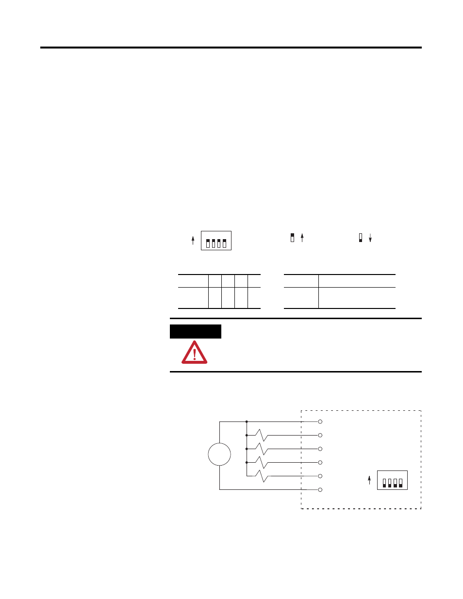
The figure below indicates wiring connections for four 24V dc
outputs. Switches of SW2 are OFF for this output voltage.
The outputs are not electrically isolated from each other. (They are
referenced to the same output common terminal.) However, outputs
are isolated from the rest of the circuitry to a level of 1500 volts.
Switch
1
2
3
4
Position
Output voltage range
Output
0
1
2
3
ON
OFF
4.5-10V dc
10-30V dc
ATTENTION
All switches of SW2 must be ON or all switches must
be OFF. Permanent damage may result if some are
ON and some are OFF.
1 2 3 4
ON
OFF
Dip switch SW2
ON postion
OFF postion
OUT 0
OUT 1
OUT 2
OUT 3
VDC
DC COM
wiring terminals
+
–
HSCE module
1 2 3 4
ON
OFF
Dip switch SW2
User Supplied
24V dc