Input and output connections, Input and output connections -7, Discrete output wiring – Rockwell Automation 1746-HSCE,D17466.5 High-Speed Counter Module User Manual
Page 51: Limit switch and encoder input wiring, Output input
Publication 1746-UM006B-EN-P - August 2005
Installation and Wiring 3-7
Input and Output
Connections
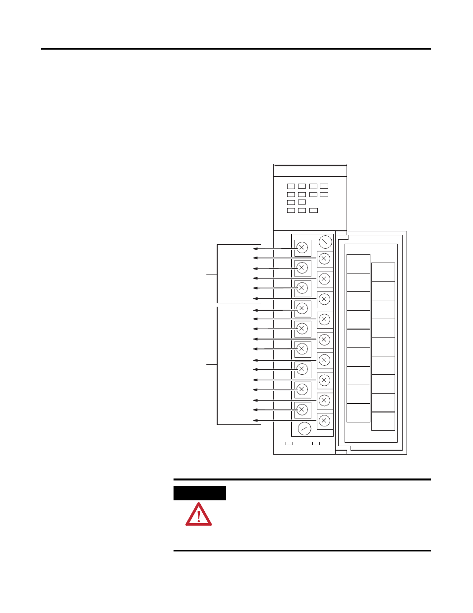
Input and output wiring terminals are located on the front of the
module, behind the terminal cover. When you connect input and
output devices, you will also be concerned with the settings of dip
switch SW1 (input connections), dip switch SW2 (output
connections), and jumper JW1 (limit switch input connections). Refer
to Dip Switch and Jumper Locations beginning on page 3-2 for the
location and description of SW1, SW2, and JW1.
VDC
OUT 1
OUT 3
A+
A–
Z+
Z–
LS COM
OUT 0
OUT 2
DC COM
B+
B–
Not used
Not used
LS(24VDC)
LS(12VDC)
LS(5VDC)
FAULT
1
2
3
4
5
6
7
0
A
B
Z
LS
VDC
OUT 0
OUT 1
OUT 2
OUT 3
A+
A–
Not used
Z+
Z–
LS COM
DC COM
B+
B–
Not used
LS (24 VDC)
LS (12 VDC)
LS (5 VDC)
OUTPUT
INPUT
HSCE
Discrete Output Wiring
VDC must be externally supplied by the user.
See page 3-8 for output wiring.
Limit Switch and Encoder Input Wiring
See pages 3-11 through 3-15 for input wiring.
ATTENTION
Do not use incandescent lamps as output indicators.
The high peak inrush current required to heat the
filament can damage the module’s output circuits.
Use LED type indicators that satisfy the output circuit
ratings, such as Allen-Bradley 800A and 800T LED
indicators.