Pulse counter state, Rate measurement, Pulse counter state -11 – Rockwell Automation 1746-HSCE,D17466.5 High-Speed Counter Module User Manual
Page 29: Rate measurement -11
Publication 1746-UM006B-EN-P - August 2005
Module Operation 2-11
Pulse Counter State
When the SLC processor enters run or test mode, the Accumulated
Count is reset to 0. It is held at 0 until the user program completes
module configuration and the Function Control bit is set to 1. If the
Function Control bit is reset to 0, the counter will again be reset and
held at 0 until the Function Control bit returns to 1.
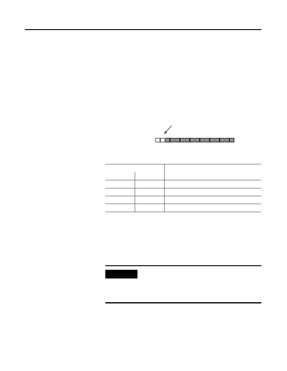
The counter state is available to the user program in the Pulse Counter
State field (I:e.0/14-15). This field is defined as follows:
Pulse Counter State - bits 14, 15
Rate Measurement
Using the Rate Counter, the module measures the frequency of the
input pulses in the range of -32767 Hz to 32767 Hz. The resulting
value is available in the Rate Measurement word (I:e.3). The number
of pulses counted in the interval is made available in the Rate Period
Count word (I:e.2).
Status Word Bits
Pulse Counter State
15
14
0
0
stopped
0
1
running
1
0
undefined
1
1
hold
Status Word, Word 0
Bit Number (decimal)
Pulse Counter State bits
15 14 13 12 11 10 9
8
7
6
5
4
3
2
1
0
I:e.0
IMPORTANT
If the input pulse rate is above 32,767 Hz, a Rate
Measurement Overflow occurs. The Rate
Measurement Overflow bit (I:e.0/5) will then be set
to 1. Refer to Rate Measurement Overflow located in
Chapter 5.