Micrologix 1500 multi-drive mode example program – Rockwell Automation 1769-SM2 Compact I/O DSI/Modbus Communication Module User Manual
Page 92
6-12
MicroLogix 1500 Example Ladder Programs
MicroLogix 1500 Multi-Drive Mode Example Program
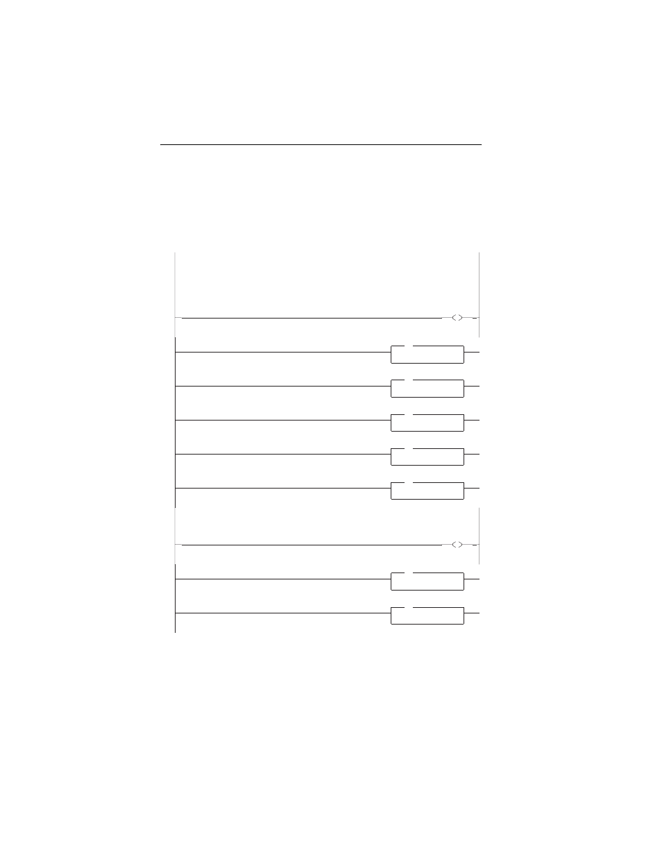
Figure 6.5 Example MicroLogix 1500 Multi-Drive Ladder Logic Main Routine
MicroLogix 1500 w/ 1769-SM2 in Multi-Drive mode
In this Multi-Drive example program, the channels are utilized as follows:
Channel 1 - Connected to 5 PowerFlex 4/40 drives (maximum allowed)
Channel 2 - Connected to 5 PowerFlex 4/40 drives (maximum allowed)
Channel 3 - Configured for Modbus RTU Master mode and connected to 1 PowerFlex 70 drive (with 20-COMM-H adapter)
This rung enables the 1769-SM2 to send the Channel 1 Logic Command and Reference words to the drives.
0000
O:1
0
1769-SM2
Channel 1
Enable
Channel 1 Drive 0 Subroutine
0001
JSR
Jump To Subroutine
SBR File Number
U:3
JSR
Channel 1 Drive 1 Subroutine
0002
JSR
Jump To Subroutine
SBR File Number
U:4
JSR
Channel 1 Drive 2 Subroutine
0003
JSR
Jump To Subroutine
SBR File Number
U:5
JSR
Channel 1 Drive 3 Subroutine
0004
JSR
Jump To Subroutine
SBR File Number
U:6
JSR
Channel 1 Drive 4 Subroutine
0005
JSR
Jump To Subroutine
SBR File Number
U:7
JSR
This rung enables the 1769-SM2 to send the Channel 2 Logic Command and Reference words to the drives.
0006
O:1
1
1769-SM2
Channel 2
Enable
Channel 2 Drive 0 Subroutine
0007
JSR
Jump To Subroutine
SBR File Number
U:8
JSR
Channel 2 Drive 1 Subroutine
0008
JSR
Jump To Subroutine
SBR File Number
U:9
JSR