Rockwell Automation 1769-SM2 Compact I/O DSI/Modbus Communication Module User Manual
Page 145
ControlLogix w/1769-ADN DeviceNet Example Ladder Program
8-15
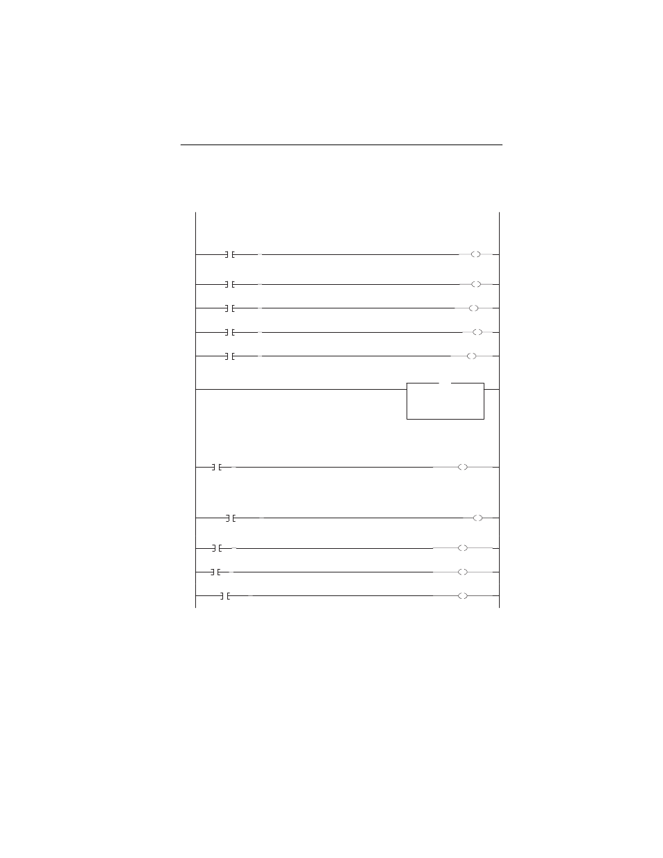
Figure 8.19 Example ControlLogix Ladder Logic CH1 Subroutine
1769-SM2 Channel 1 Subroutine
The following rungs display some of the Logic Status bits from the drive. Refer to Appendix D in the 1769-SM2 user manual
for additional information about the Logic Status word.
0
SM2_Input_Data[3].0
CH1_Ready
i
1
SM2_Input_Data[3].1
CH1_Active
2
SM2_Input_Data[3].3
CH1_Forward
3
SM2_Input_Data[3].7
CH1_Fault
4
SM2_Input_Data[3].8
CH1_At_Speed
This rung displays the Feedback from the drive. An integer represents the xxx.x Hz format (decimal is implied) used by the
drive, so a displayed value of "300" equates to 30.0 Hz.
5
Move
Source SM2_Input_Data[4]
100
Dest
CH1_Feedback
100
MOV
The following rungs display some of the Logic Command bits sent to the drive. Refer to Appendix D in the 1769-SM2 user
manual for additional information about the Logic Command word.
6
CH1_Stop
SM2_Output_Data[1].0
i
This rung unlatches the contact that turns on the Start command when the drive is not communicating with the 1769-SM2.
This prevents the drive from immediately starting when communications are restored. If an immediate start is desired for an
application, this rung could be deleted.
7
/
CH1_Valid_Data
U
CH1_Start
8
CH1_Start
SM2_Output_Data[1].1
9
CH1_Jog
SM2_Output_Data[1].2
10
CH1_Clear_Fault
SM2_Output_Data[1].3