Unshielded connector grounding requirements – Rockwell Automation 1769-SM2 Compact I/O DSI/Modbus Communication Module User Manual
Page 35
Installing the Module
2-13
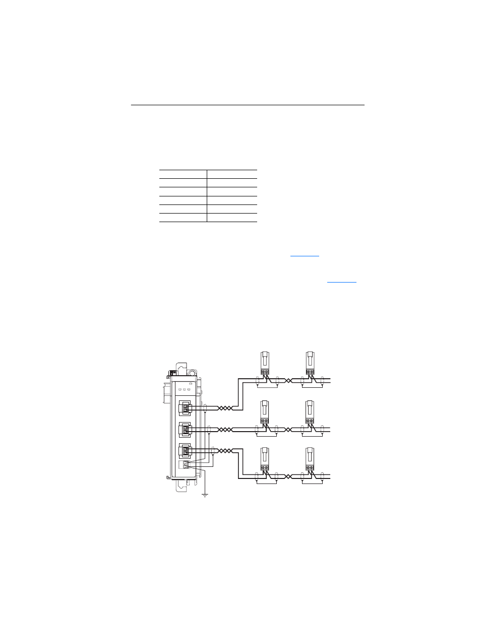
Unshielded Connector Grounding Requirements
When using twisted pair network wiring with unshielded
AK-U0-RJ45-TB2P connectors, ground the RJ45 socket on the drive by
connecting the drive chassis ground power terminal to the I/O block
shield terminal.
The 1769-SM2 module’s RJ45 connectors (CH1, CH2, and CH3), which
are electrically common, should be grounded by attaching a drain wire
from the 1769-SM2 terminal block (item 11 in
) to a grounded,
conductive surface (i.e. metal panel). If shielded cable (not required) is
used, the cable shield should also be connected to the chassis by
attaching the cable shield to the 1769-SM2 terminal block (
Good wiring practice dictates that the cable shield be terminated to the
chassis at only one point along the cable to prevent ground loops from
occurring. The chassis terminal block on the 1769-SM2 module is
provided as a convenient place for this termination.
Figure 2.7 Unshielded Connector Grounding Details
Drive
Drive I/O Block
PowerFlex 4
Terminal 16
PowerFlex 4M
Terminal 16
PowerFlex 40
Terminal 19
PowerFlex 40P
Terminal 19
PowerFlex 400
Terminal 20
DSI / Modbus RTU
MODULE
CH1
CH2
CH3
C
H
1
C
H
2
C
H
3
To Drive 1
To Drive 2
. . .
To Drive 1
To Drive 2
. . .
To Drive 1
To Drive 2
. . .