Setting the fault configuration parameters, Setting drive node addresses (multi-drive mode – Rockwell Automation 1769-SM2 Compact I/O DSI/Modbus Communication Module User Manual
Page 54
3-16
Configuring the Module
Setting the Fault Configuration Parameters
If you set Parameter 04 - [Idle Action 1], 19 - [Idle Action 2], or 34 -
[Idle Action 3] to “Send Flt Cfg,” the values in the following 1769-SM2
module parameters are sent to the drive after an idle action occurs. You
must set these parameters to values required by your application.
Changes to these parameters take effect immediately. A reset is not required.
When using the 1769-SM2 module in Multi-Drive mode, a unique node
address must be set for each drive. Use the following parameters to set
the drive node addresses:
Important: The setting for each of these parameters must match the
drive Parameter 104 - [Comm Node Addr] value for each
respective drive. Each drive node address must be unique
(no duplicate node addresses).
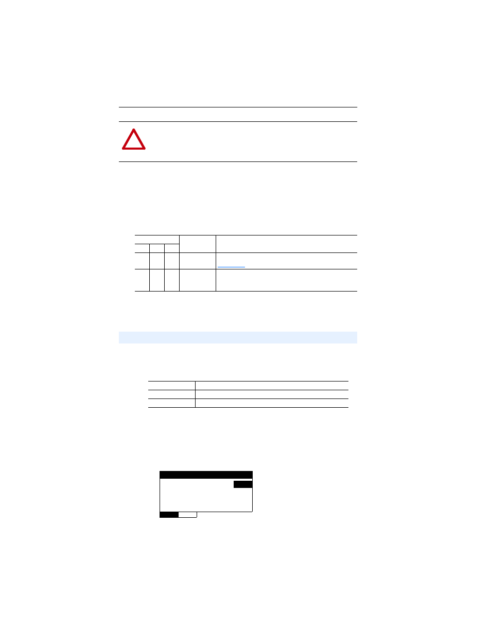
Figure 3.16 Example Node Address HIM Screen for CH1 Drive 0
!
ATTENTION: Idle Action is NOT available for RTU Master
operation in Multi-Drive mode. The connected RTU Slave devices will
take their respective internal fault actions in response to receiving no
communications from the 1769-SM2 module.
Parameter No.
Name
Description
CH1 CH2 CH3
05
20
35
Flt Cfg Logic
A 16-bit value sent to the drive for Logic Command. Refer to
for a description of the Logic Command bits.
06
21
36
Flt Cfg Ref
A 16-bit value sent to the drive as a Reference. Format is:
xxx.x Hz. for PowerFlex 4/4M/40/40P drives
xxx.xx Hz. for PowerFlex 400 drives
Setting Drive Node Addresses (Multi-Drive Mode Only)
For CH1 Drives
Parameters 09 - [Drv 0 Addr 1] through 13 - [Drv 4 Addr 1]
For CH2 Drives
Parameters 24 - [Drv 0 Addr 2] through 28 - [Drv 4 Addr 2]
For CH3 Drives
Parameters 39 - [Drv 0 Addr 3] through 43 - [Drv 4 Addr 3]
Drv 0 Addr 1
Parameter:
#
009
100
VALUE
LIMITS
SEL
Default:
100
Minimum: 1
Maximum: 247