Chapter 4, Understanding the i/o image, 4understanding the i/o image – Rockwell Automation 1769-SM2 Compact I/O DSI/Modbus Communication Module User Manual
Page 61: Chapter
Chapter
4
Understanding the I/O Image
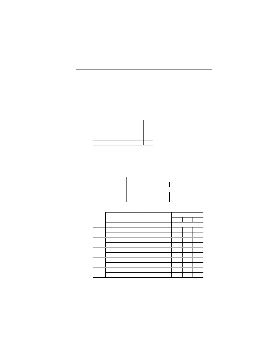
This chapter provides information and examples of the 1769-SM2
module I/O image, including Module Control/Status, Logic Command/
Status, and Reference/Feedback.
The I/O image for the 1769-SM2 module varies based on its selected
operating mode (Single or Multi-Drive), and the settings for Parameters
07 - [DSI I/O Cfg 1], 22 - [DSI I/O Cfg 2], and 37 - [DSI I/O Cfg 3].
Table 4.A 1769-SM2 Module I/O Image Table for Single Mode
Table 4.B 1769-SM2 Module I/O Image Table for Multi-Drive Mode
Note that the I/O words for each channel are contiguous, keeping the
required I/O space to a minimum. For example, to connect one
PowerFlex 40 drive in Single mode and perform control (Logic
Command/Status and Reference/Feedback), only 3 words of I/O are
Topic
Page
Output Image
Input Image
Word
CH1
CH2
CH3
Module Control Word
Module Status Word
0
Logic Command
Logic Status
1
3
5
Reference
Feedback
2
4
6
Output Image
Input Image
Word
CH1
CH2
CH3
Module Control Word
Module Status Word
0
Drive 0
Logic Command
Logic Status
1
11
21
Reference
Feedback
2
12
22
Drive 1
Logic Command
Logic Status
3
13
23
Reference
Feedback
4
14
24
Drive 2
Logic Command
Logic Status
5
15
25
Reference
Feedback
6
16
26
Drive 3
Logic Command
Logic Status
7
17
27
Reference
Feedback
8
18
28
Drive 4
Logic Command
Logic Status
9
19
29
Reference
Feedback
10
20
30