Connecting drive(s) to the module, Single mode, Connecting drive(s) to the module -10 – Rockwell Automation 1769-SM2 Compact I/O DSI/Modbus Communication Module User Manual
Page 32
2-10
Installing the Module
8. Connect the 1769-SM2 module and adjacent modules together by
locking (fully left) the bus levers on the 1769-SM2 module and the
right-side adjacent module.
9. Replace the mounting screws (or snap the module onto the DIN rail).
10. Plug the appropriate communications cable into its respective port on
the 1769-SM2 module.
11. Restore 1769-SM2 module configuration using an appropriate
configuration tool.
NOTE: For Single or Multi-Drive mode, there is a maximum cable
distance limit per channel. See
DSI Cable Requirements on page A-2
for
more information.
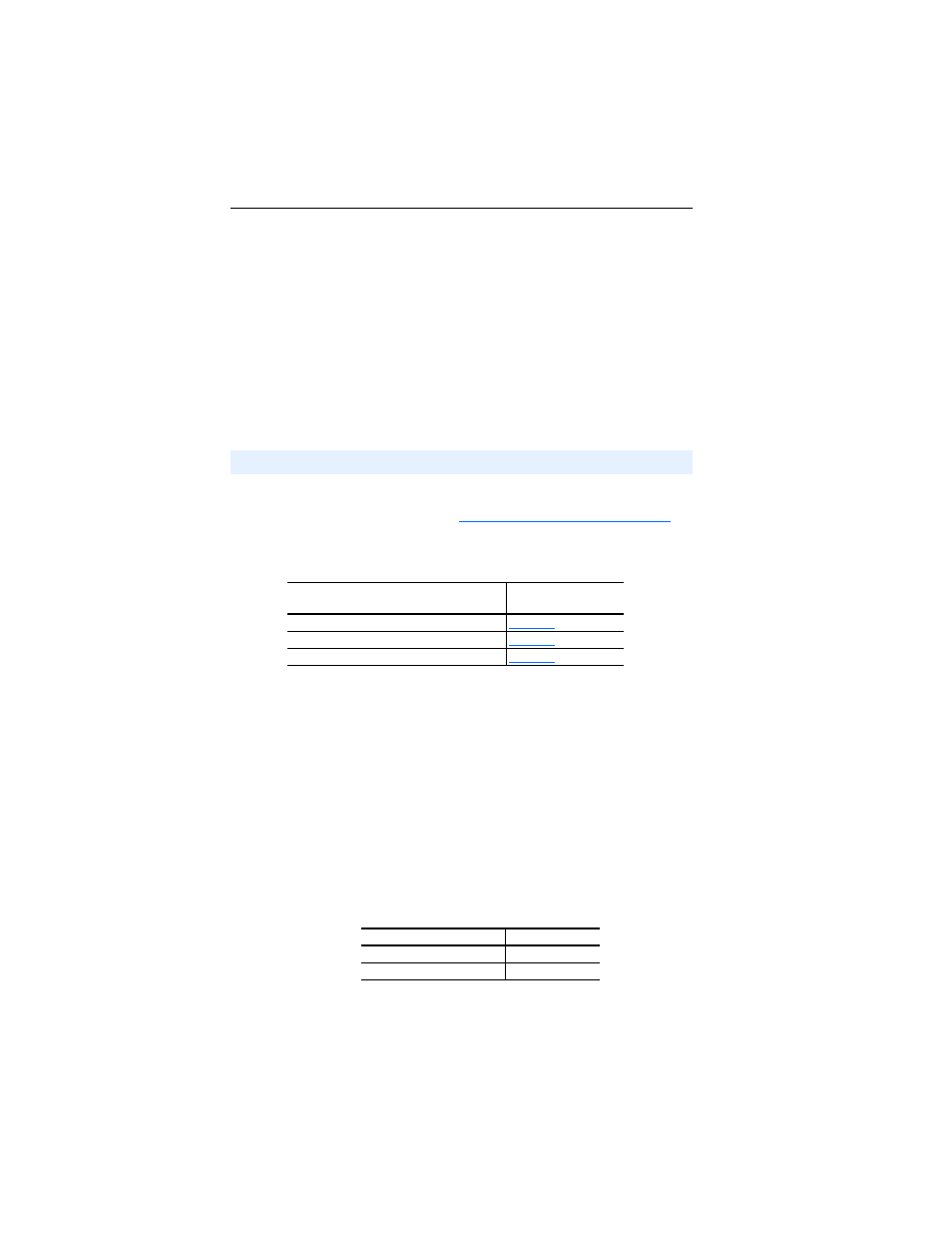
For network wiring diagram examples, see the following figures:
Single Mode
When the 1769-SM2 module is operated in Single drive mode, each
drive is directly connected to a channel port (CH1, CH2 or CH3) on the
module. Use either a 22-RJ45CBL-C20 communications cable for each
channel or AK-U0-RJ45-TB2P terminal block connectors and twisted
pair network wiring (Belden No. 3105A or equivalent).
Important: When connecting a drive to the channel port using
AK-U0-RJ45-TB2P terminal block connectors and twisted
pair network wiring, the following drive parameters MUST
be configured to the settings shown so that the 1769-SM2
module will communicate with the drive:
Changes to these drive parameters require the drive to be
reset for the new settings to take effect.
Connecting Drive(s) to the Module
1769-SM2 Operating Mode
Network Wiring
Diagram Example…
Single mode (Default)
Multi-Drive mode
Multi-Drive mode with Modbus RTU Master
Drive Parameter
Setting
A103 - [Comm Data Rate]
“4” (19.2K)
A107 - [Comm Format]
“0” (RTU 8-N-1)