Validate the system – Rockwell Automation 1762-Lxxxx MicroLogix 1200 Programmable Controllers User Manual
Page 149
Publication 1762-UM001G-EN-P - March 2011
System Loading and Heat Dissipation F-7
Validate the System
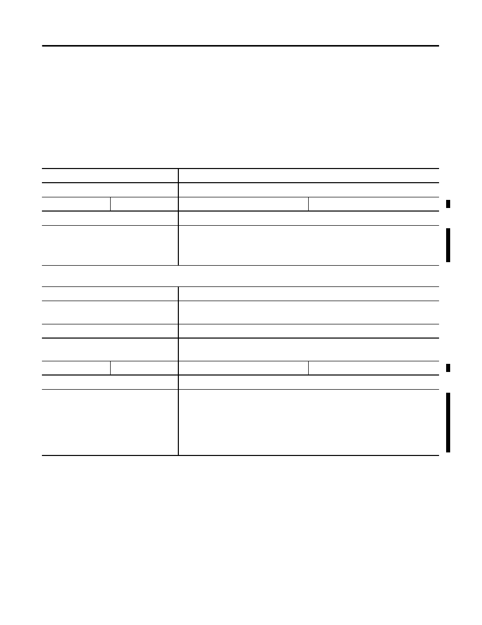
The example systems shown in Table F.11 and Table F.12 are verified to be
acceptable configurations. The systems are valid because:
•
Calculated Current Values < Maximum Allowable Current Values
•
Calculated System Loading < Maximum Allowable System Loading
Table F.11 Validating Systems using 1762-L40AWA, 1762-L40BXB, 1762-L40AWAR or 1762-L40BXBR
Maximum Allowable Values
Calculated Values
Current:
Current (Subtotal 1 from Table F.9 + Subtotal 2 from Table F.10):
600 mA at 5V dc
500 mA at 24V dc
0 mA + 435 mA = 435 mA at 5V dc
120 mA + 285 mA = 405 mA at 24V dc
System Loading:
System Loading:
15 Watts
= (4.5 mA x 5V) + (405 mA x 24V)
= (2175 mW) + (9720 mW)
= 11,895 mW
= 11.90 Watts
Table F.12 Validating Systems using 1762-L40BWA or 1762-L40BWAR
Maximum Allowable Values
Calculated Values
Current for Devices Connected to the +24V dc
Sensor Supply:
Sum of all current sensors
400 mA at 24V dc
150 mA at 24V dc (example sensor value)
Current for MicroLogix Accessories and
Expansion I/O:
Current (Subtotal 1 from Table F.9 + Subtotal 2 from Table F.10):
600 mA at 5V dc
500 mA at 24V dc
0 mA + 435 mA = 435 mA at 5V dc
120 mA + 285 mA = 405 mA at 24V dc
System Loading:
System Loading:
16 Watts
= (150 mA x 24V) + (435 mA x 5V) + (405 mA x 24V)
= (3600 mW) + (2175 mW) + (9720 mW)
= 15,495 W
= 15.50 Watts