Rockwell Automation 1762-Lxxxx MicroLogix 1200 Programmable Controllers User Manual
Page 147
Publication 1762-UM001G-EN-P - March 2011
System Loading and Heat Dissipation F-5
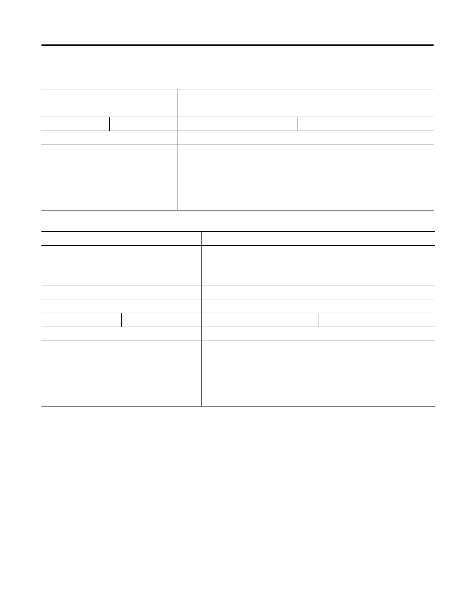
Table F.7 Validating Systems using 1762-L24AWA, 1762-L24BXB, 1762-L24AWAR or 1762-L24BXBR
Maximum Allowable Values
Calculated Values
Current:
Current (Subtotal 1 from Table F.5 + Subtotal 2 from Table F.6.):
400 mA at 5V dc
350 mA at 24V dc
mA at 5V dc
mA at 24V dc
System Loading:
System Loading:
10.4 Watts
= (________ mA x 5V) + (________ mA x 24V)
= __________ mW + __________ mW
= __________ mW
= __________ W
Table F.8 Validating Systems using 1762-L24BWA or 1762-L24BWAR
Maximum Allowable Values
Calculated Values
Current for Devices Connected to the +24V dc Sensor
Supply:
Sum of all sensor currents
Include 1761-NET-AIC here rather than in Table F.5, if it is powered externally by
the sensor supply
250 mA at 24V dc
mA at 24V dc
Current for MicroLogix Accessories and Expansion I/O: Current (Subtotal 1 from Table F.5 + Subtotal 2 from Table F.6.)
400 mA at 5V dc
350 mA at 24V dc
mA at 5V dc
mA at 24V dc
System Loading:
System Loading:
12 Watts
= (________ mA x 24 V) + (________ mA x 5V) + (________ mA x 24 V)
= __________ mW + __________ mW + __________ mW
= __________ mW
= __________ W