Example dh-485 connections, Dh-485 network with a micrologix 1200 controller – Rockwell Automation 1762-Lxxxx MicroLogix 1200 Programmable Controllers User Manual
Page 139
Publication 1762-UM001G-EN-P - March 2011
Connect to Networks via RS-232 Interface E-9
maximum node address of your controllers. It should be set to the highest
node address being used.
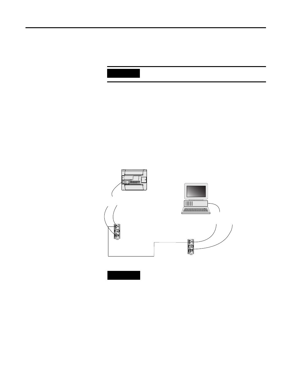
Example DH-485 Connections
The following network diagrams provide examples of how to connect
MicroLogix 1200 controllers to the DH-485 network using the Advanced
Interface Converter (AIC+, catalog number 1761-NET-AIC). For more
information on the AIC+, see the Advanced Interface Converter and
DeviceNet Interface Installation Instructions, Publication 1761-IN002.
DH-485 Network with a MicroLogix 1200 Controller
IMPORTANT
All devices should be set to the same maximum node
address.
TERM
A
B
COM
SHLD
CHS GND
TX
TX
PWR
TX
DC SOURCE
CABLE
EXTERNAL
TERM
A
B
COM
SHLD
CHS GND
TX
TX
PWR
TX
DC SOURCE
CABLE
EXTERNAL
(3)
(1)
(2)
(3)
(1)
(2)
MicroLogix
1200
connection from port 1 or
port 2 to MicroLogix
1761-CBL-AM00 or
1761-CBL-HM02
+24V dc user supply
1761-CBL-AP00 or
1761-CBL-PM02
1747-CP3 or
1761-CBL-AC00
1761-CBL-AP00 or
1761-CBL-PM02
connection from port 1
or port 2 to PC
+24V dc user supply
AIC+
AIC+
DH-485
(1) DB-9 RS-232 port
(2) mini-DIN 8 RS-232 port
(3) RS-485 port
TIP
Series C or higher cables are required.