Analog i/o connections, Analog inputs – Rockwell Automation 1336T ControlNet Frn1.02 Rev 1.5 User Manual
Page 21
1–6
Installing and Wiring Your ControlNet Adapter Board
Publication 1336 FORCE–5.18 ––March, 1999
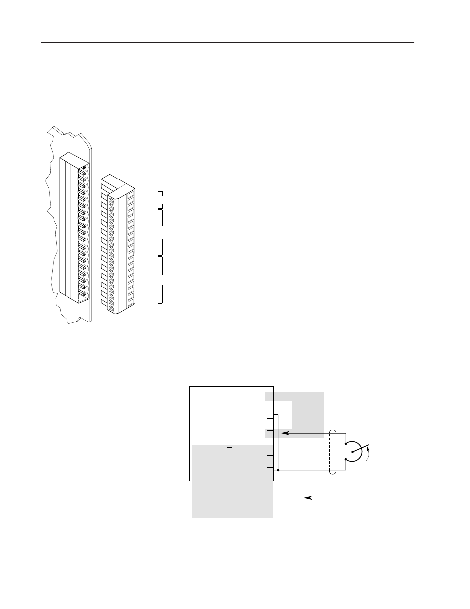
You can access the analog I/O connections at terminal block TB21.
There are four analog inputs and four analog outputs. Each of the
analog I/O parameter have scale and offset parameters. The analog
inputs can be linked to any linkable sink parameter, and the analog
outputs can receive information from any parameter in the drive.
The drive increments the analog I/O every two milliseconds.
Analog Inputs
The ControlNet Adapter Board has 4 analog inputs that have a range
of
±
10V and a digital resolution of 12 bits. These inputs are
differential inputs with noise rejection filtering. Each input has a
gain and offset adjustment.
The A/D converter is a 12-bit device where an input value of +10V
results in a digital value of 2048. Likewise, an input value of -10V
results in a digital output value of -2048.
Chapter 2, Starting Up, describes the parameters associated with
scaling analog values.
For an analog input to control a function, you need to:
1. Link the analog input parameter(s) to a parameter such as
velocity reference.
2. Set up the scale and offset parameters associated with that analog
input parameter.
The typical analog input connections for unidirectional operation are
shown as follows:
COM (POWER SUPPLY COMMON)
IN + (ANALOG IN)
+ 10V
DC (POWER SUPPLY)
IN – (ANALOG IN)
18
TO TE
(SIGNAL GROUND TERMINAL BLOCK)
REFERENCE POT
2.5 k
Ω
MINIMUM
TB21
Connect to
Either 17 or 19
(ONLY ONE)
Note: Connect to Only One Set of Inputs
— IN4+ and IN4–
— IN3+ and IN3–
— IN2+ and IN2–
— IN1+ and IN1–
17
– 10V
DC (POWER SUPPLY) 19
ADC
Analog I/O Connections
19
TB21
1
IN1 + (9)
COM4 (8)
OUT4 (7)
COM3 (6)
OUT3 (5)
COM2 (4)
OUT2 (3)
COM1 (2)
OUT1 (1)
– 10V (19)
REF
COM (18)
+ 10V (17)
IN4 – (16)
IN4 + (15)
IN3 – (14)
IN3 + (13)
IN2 – (12)
IN1 – (10)
IN2 + (11)
ADC
DAC