Chapter, Chapter objectives – Rockwell Automation 1336T ControlNet Frn1.02 Rev 1.5 User Manual
Page 16
Chapter
1
Publication 1336 FORCE–5.18 ––March, 1999
Installing and Wiring Your
ControlNet Adapter Board
Chapter 1 provides information so that you can:
•
mount the ControlNet Adapter Board
•
configure and connect the communications
•
configure and set up the discrete inputs and analog I/O
Important: The installation and wiring information in this manual
is specific to the ControlNet Adapter Board. For
information about mounting the drive, connecting the
motor leads, or connecting the power, refer to the 1336
FORCE user manual.
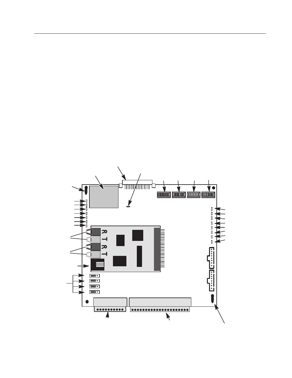
The following illustration shows the ControlNet Adapter Board.
Keyed Mounting Slot
Terminal Block TB20:
Discrete I/O Connections
Terminal Block TB21:
Analog I/O Connections
J1 Control Board Interface
Keyed Mounting Slot
BRAM Jumper J3
Voltage Selection
Inputs
AP Status –– D1
AP Status –– D2
Fault Out –– D4
Ext Fault –– D5
Norm Stop –– D7
Motor Thermo –– D9
Drive Enable –– D11
DP Status –– D3
DP Status –– D6
Primary Status –– D8
Primary Status –– D10
Primary Status –– D12
Redundant Status –– D13
Redundant Status –– D14
Redundant Status –– D15
Configuration DIP Switches
Not
Used
Not Used In
This Application
U2
U3
U4
U5
D3 – Red
Solid = Soft Fault
Blinking = Hard Fault
D6 – Green
Solid = No Fault
Blinking = Warning
D8 – Red
Mimics Primary Plug Channel LED
D10 – Yellow
Blinking 1Hz = Operational
D12 – Green
Mimics Primary Plug Channel LED
D13 – Red
Mimics Redundant Channel LED
D14 – Yellow
Blinking 1 Hz = Operational
D15 – Green
Mimics Redundant Channel LED
Node
Address
J11
J10
J9
J8
Primary
Channel
Redundant
Channel
Port 1
Port 2
Language Module
Network
Access Port
1
10
1
19
Plug Board
Chapter Objectives