Rockwell Automation 150 SMC-Flex User Manual User Manual
Page 130
A-4
Specifications
➀
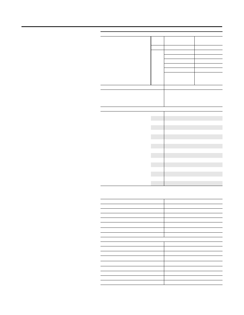
Heatsink fans can be powered by either 110/120V AC or 220/240V AC.
Power Requirements
Control Module, 1…480 A
120…
240V AC
Transformer
75 VA
24V AC
Transformer
130 VA
24V DC
Inrush Current
5 A
Inrush Time
250 ms
Transient Watts
60 W
Transient Time
500 ms
Steady State Watts
24 W
Minimum
Allen-Bradley Power
Supply
1606-XLP50E
Control Module, 625…1250 A
751 VA (recommended 800 VA)
Heatsink Fan(s) (A)
➀
5…135 A, 20 VA
201…251 A, 40 VA
317…480 A, 60 VA
625…1250 A, 150 VA
Steady State Heat Dissipation with Control and Fan Power (W)
Controller Rating (A)
5
70
25
70
43
81
60
97
85
129
108
91
135
104
201
180
251
198
317
225
361
245
480
290
625
446
780
590
970
812
1250
1222
Auxiliary Contacts
•
19/20 Aux #1
•
29/30 Aux #2
•
31/32 Aux #3
•
33/34 Aux #4
Type of Control Circuit
Electromagnetic relay
Number of Contacts
1
Type of Contacts
programmable N.O./N.C.
Type of Current
AC
Rated Operational Current
3 A @ 120V AC, 1.5 A @ 240V AC
Conventional Thermal Current I
th
AC/DC
5 A
Make/Break VA
3600/360
Utilization Category
AC-15/DC
PTC Input Ratings
Response Resistance
3400
Ω
±150
Ω
Reset Resistance
1600
Ω
±100
Ω
Short-Circuit Trip Resistance
25
Ω
±10
Ω
Max. Voltage at PTC Terminals (R
PTC
= 4 k
Ω
)
< 7.5V
Max. Voltage at PTC Terminals (R
PTC
= open)
30V
Max. No. of Sensors
6
Max. Cold Resistance of PTC Sensor Chain
1500
Ω
Response Time
800 ms
Tach Input
0…5V DC. 4.5V DC = 100% Speed