Rockwell Automation 20-COMM-D DeviceNet Adapter Series B FRN 2.xxx User Manual
Page 71
Configuring the I/O
4-29
20-COMM-D DeviceNet Adapter User Manual
Publication 20COMM-UM002G-EN-P
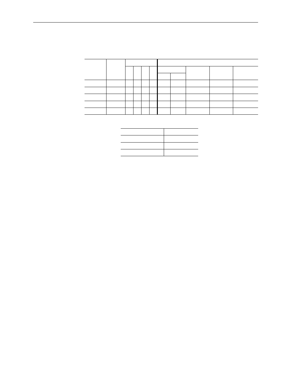
Table 4.G Drives with 32-bit Reference/Feedback and 32-bit Datalinks
These products include the following:
g. Set the scan rate for the selected data exchange method.
For more information about scan rates, see RSNetWorx for
DeviceNet online help.
h. Click OK.
If a Scanner Configuration Applet appears, click Yes to continue.
The Edit I/O Parameters screen closes and then the 1771-SDN
Scanlist tab screen reappears.
12. Click the Input tab to display the input registers for the 1771-SDN
scanner.
Important: If your RSLogix 5 project requires a different memory
selection than the default setting for the drive input image,
set the Memory field to the appropriate setting. For this
example, the default setting of Block Xfer 62 and its
corresponding N-files are used.
• PowerFlex 700S drives with Phase I or Phase II control
• PowerFlex 753 drives
• PowerFlex 700L drives with 700S control
• PowerFlex 755 drives
Logic
Command/
Status
Ref/Fdbk
(32-bit)
Datalinks (32-bit) User Configured Settings
A
B
C
D
Size in Bytes
Par. 13 -
[DPI I/O Cfg]
Par. 25 -
[M-S Input]
Par. 26 -
[M-S Output]
Input Output
✔
✔
8
8
…0 0001
…0 0001
…0 0001
✔
✔
✔
16
16
…0 0011
…0 0011
…0 0011
✔
✔
✔
✔
24
24
…0 0111
…0 0111
…0 0111
✔
✔
✔
✔
✔
32
32
…0 1111
…0 1111
…0 1111
✔
✔
✔
✔
✔
✔
40
40
…1 1111
…1 1111
…1 1111
Data Exchange Method
Rate Field to Set
Polled
Poll Rate
Change of State
Heartbeat Rate
Cyclic
Send Rate