Setting the node address switches, Setting the node address switches -2, Setting the node address – Rockwell Automation 20-COMM-D DeviceNet Adapter Series B FRN 2.xxx User Manual
Page 20
2-2
Installing the Adapter
20-COMM-D DeviceNet Adapter User Manual
Publication 20COMM-UM002G-EN-P
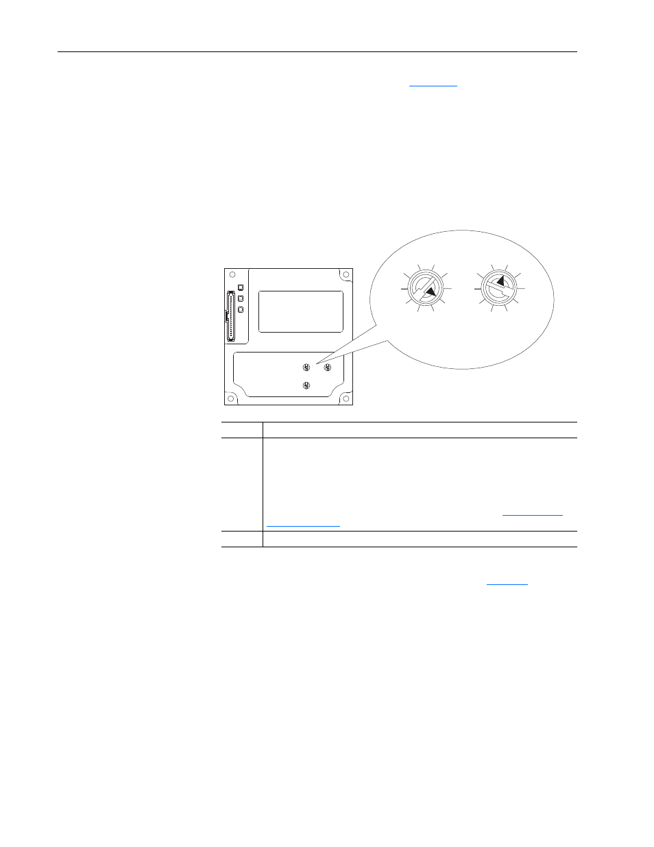
Setting the Node Address
Switches
Set the adapter Node Address switches (
Figure 2.1
) by rotating the switches
to the desired value for each digit.
Important: Each node on the DeviceNet network must have a unique
address. Set the node address before power is applied because
the adapter uses the node address it detects when it first
receives power. To change a node address, you must set the new
value and then remove and reapply power to (or reset) the
adapter.
Figure 2.1 Setting Adapter Node Address Switches
The Node Address switch settings can be verified by viewing Parameter 04
- [DN Addr Act] or Diagnostic Device Item number 30 (
) with any
of the following drive configuration tools:
• PowerFlex HIM
• Connected Components Workbench software, version 1.02 or later
• DriveExplorer software, version 2.01 or later
• DriveExecutive software, version 3.01 or later
Setting
Description
0…63
The node address used by the adapter if the Node Address switches are enabled.
The default switch setting is 63. Node address 63 is also the default address used by all
uncommissioned devices. We recommend that you do not use this address as the final
adapter address.
Important: If the Data Rate switch is set to ‘PGM’ (Program), the adapter uses the value
stored in
Parameter 03 - [DN Addr Cfg] for the node address. See
.
64…99
Do not use. The adapter will not recognize these addresses.
Tens
Digit
Ones
Digit
2
1
0
9
8
3
4
5
6
7
2
1
0
9
8
3
4
5
6
7