Rockwell Automation 20-COMM-D DeviceNet Adapter Series B FRN 2.xxx User Manual
Page 189
Adapter Parameters
B-3
20-COMM-D DeviceNet Adapter User Manual
Publication 20COMM-UM002G-EN-P
11
[Idle Flt Action]
Sets the action that the adapter and drive will take
if the adapter detects that the controller is in
program mode or faulted. This setting is effective
only if I/O that controls the drive is transmitted
through the adapter. When the controller is put
back in Run mode, the drive will automatically
receive commands over the network again.
Default:
0 = Fault
Values:
0 = Fault
1 = Stop
2 = Zero Data
3 = Hold Last
4 = Send Flt Cfg
Type:
Read/Write
Reset Required: No
12
[DN Active Cfg]
Displays the source from which the adapter node
address and data rate are taken. This will either be
‘1’ (Switches) or ‘0’ (EEPROM) in which the
address from
Parameter 03 - [DN Addr Cfg] and
the data rate from
Parameter 05 - [DN Rate Cfg]
is stored. The source is determined by the settings
of the adapter switches.
Values:
0 = EEPROM
1 = Switches
Type:
Read Only
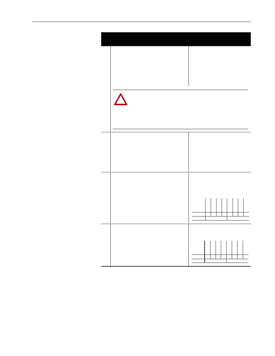
13
[DPI I/O Cfg]
Sets the I/O that is transferred through the adapter.
Default:
xxx0 0001
Bit Values:
0 = I/O Disabled
1 = I/O Enabled
Type:
Read/Write
Reset Required: Yes
14
[DPI I/O Act]
Displays the I/O that the adapter is actively
transmitting. The value of this parameter will
usually be equal to the value of
Parameter 13 -
[DPI I/O Cfg].
Bit Values:
0 = I/O Disabled
1 = I/O Enabled
Type:
Read Only
Parameter
No. Name and Description
Details
!
ATTENTION: Risk of injury or equipment damage exists. Parameter 11 - [Idle
Flt Action] lets you determine the action of the adapter and connected drive
when the controller is idle. By default, this parameter faults the drive. You can set
this parameter so that the drive continues to run, however, precautions should
be taken to verify that the setting of this parameter does not create a risk of
injury or equipment damage. When commissioning the drive, verify that your
system responds correctly to various situations (for example, a faulted
controller).
Bit
Definition
Not
Used
Not
Used
Not
Used
D
atal
ink
D
D
atal
ink
C
D
atal
ink
B
D
atal
ink
A
Cmd/Ref
Default
x
x
x
0
0
0
0
1
Bit
7
6
5
4
3
2
1
0
Bit
Definition
No
t U
se
d
No
t U
se
d
No
t U
se
d
Da
tali
nk
D
Da
tali
nk
C
Da
tali
nk
B
Da
tali
nk
A
Cm
d/
R
ef
Default
x
x
x
0
0
0
0
1
Bit
7
6
5
4
3
2
1
0