Rockwell Automation 20-COMM-D DeviceNet Adapter Series B FRN 2.xxx User Manual
Page 34
3-6
Configuring the Adapter
20-COMM-D DeviceNet Adapter User Manual
Publication 20COMM-UM002G-EN-P
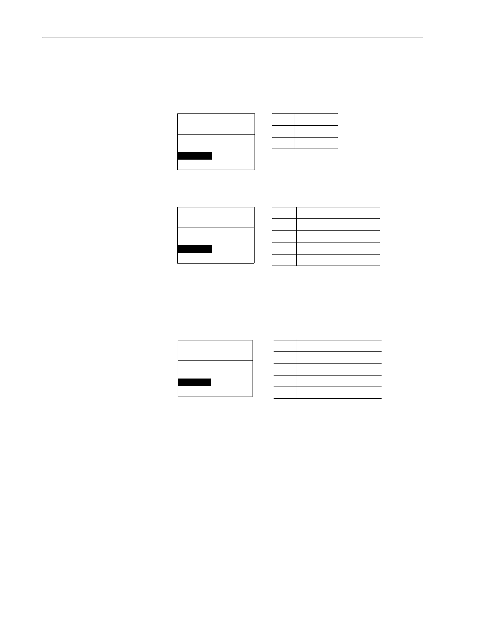
Setting the Adapter to Transmit Peer-to-Peer Data (Drive-to-Drive
Communication)
1. Verify that Parameter 41 - [Peer Out Enable] is set to ‘0’ (Off).
This parameter must be Off while you configure peer output parameters.
2. Set Parameter 39 - [Peer A Output] to select the source of the data to
output to the network.
Important: When transmitting a 32-bit Reference or 32-bit Datalink,
only Peer A Output will be available. Peer B Output cannot
be used.
3. If desired, set Parameter 40 - [Peer B Output] to select an additional
source of the data to output to the network.
4. Set Parameters 42 - [Peer Out Time] and 43 - [Peer Out Skip] to
establish the minimum and maximum intervals between Peer messages.
Because the adapter transmits Peer messages when a change-of-state
condition occurs, minimum and maximum intervals are required.
– The minimum interval ensures that the adapter does not transmit
messages on the network too often, thus minimizing network traffic.
It is set using Parameter 42 - [Peer Out Time].
– The maximum interval ensures that the adapter transmits messages
often enough so that the receiving adapters can receive recent data
and verify that communication is working or, if communication is
not working, can timeout. The maximum interval is the value of
Parameter 42 - [Peer Out Time] multiplied by the value of
Parameter 43 - [Peer Out Skip].
Value Setting
0
Off (Default)
1
On
Port 5 Device
20-COMM-D
Parameter #: 41
Peer Out Enable
0
Off
Port 5 Device
20-COMM-D
Parameter #: 39
Peer A Output
1
Cmd/Ref
Value
Description
0
Off (Default)
1
Logic Command/Reference
2…5
Datalink A, B, C, or D Input
6…9
Datalink A, B, C, or D Output
Port 5 Device
20-COMM-D
Parameter #: 40
Peer B Output
2
DL A Input
Value
Description
0
Off (Default)
1
Logic Command/Reference
2…5
Datalink A, B, C, or D Input
6…9
Datalink A, B, C, or D Output